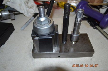
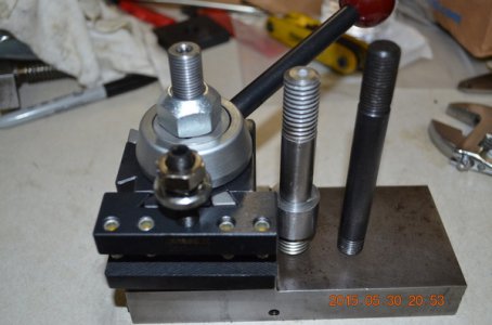
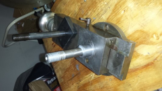
Mickey sent me some pictures on how his is put together, thanks, bud. MSKJ and I traded a ideas around on how to resolve the situation, thanks, Mark. I encountered some surprises as I took the slide apart. First I thought the original stud was just pressed in and held in place by the 2 grab screws. Found out the stud was threaded at the base and screwed on to the slide and locked in place by the 2 grab screws.
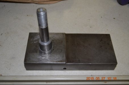
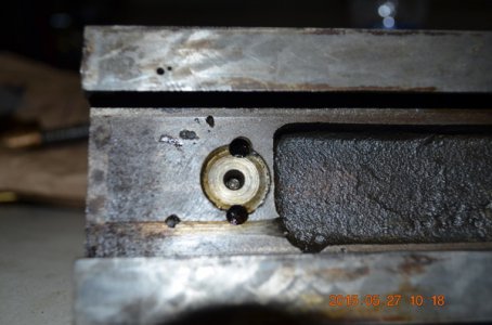
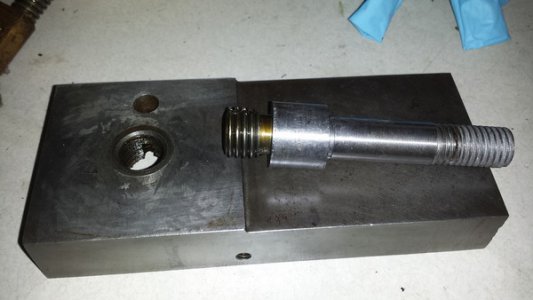
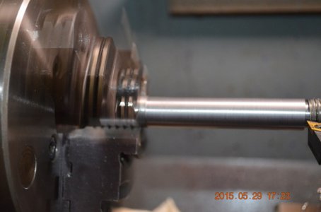
Debated whether to machine the old stud to go through the PII tool post or machine one from scratch. Took the latter. The stud base thread pitch looks like 2.5 metric. My lathe needed a different gear to do metric, so I decided to do the closest Imperial, 1/2 TPI, I figure it is not the right fit, but if I were to thread the stud slowly and use the slide threaded hole as a GO Gauge I might be able to make it work. I happen to have a rusted piece of steel of unknown type that I grabbed from the batch of steel rods and bolts from an oil field operation on the ranch I have access to, I figure I will use it to for a test run, and if destroyed I can get a different rod and start all over again
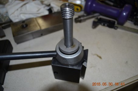
The new stud will be a hybrid between the original and PII studs,
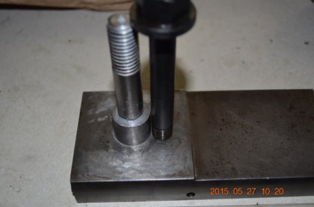
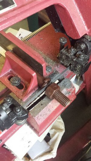
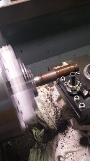
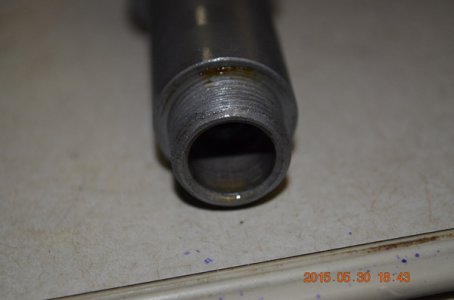
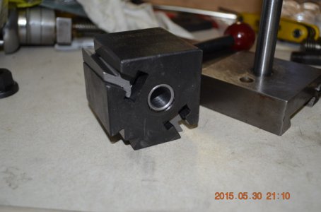
I took the measurement at the top of the PII for the clearance on how much to turn the rusted rod to. Got the measurements I needed. Instead of threading the top of the new stud to the 14 x 1.5 for the PII flange nut, since I could not thread metric I decided to 9/16 x 18 and turned down the OD to .562. Mark found a package of flange nut on eBay, but it will take days for them to arrive. In the meantime I went to a neighborhood auto parts house and picked up a wheel lug nut. The 9/16x18 is a common auto thread. The nut served as my thread Go Gauge. When test fitted the turned down and threaded rod it did not fit, went in about 3/4 in and dead headed. The sleeve inside the PII has a step ID, smaller at the bottom coincident to the threaded tenon that screws on to the PII base. Had to bore this ID to accommodate the newly machined stud.
The new stud is purposely left longer than what appears to be needed, I want to make sure I would have it go through all the way with the eBay flange nuts. I could not find any dimension on their length.
