Pictures of DRO installations on classic South Bend toolroom lathes?

rwdenney

H-M Supporter - Gold Member
H-M Supporter Gold Member
Joined
Aug 12, 2022
Messages
399
I’m planning to eventually equip my South Bend 14-1/2” lathe with a 2-axis DRO. My lathe is a toolroom version with a taper attachment, which interferes with the obvious location for the z-axis scales. And the saddle casting makes the x-axis scale not completely obvious, particularly if one wants to preserve tailstock access to working close to the spindle.

I am not needing advice on which DRO head to use—I think I can work that out myself. I hope to make my purchase of scales at the budget end of the cost spectrum.

I’m interested in seeing pictures of how people have installed scales, both optical and magnetic, on South Bend 13, 14-1/2, and 16” S-series lathes from the 40’s through the 70’s, particularly those with taper attachments. Any pictures are welcome, but of course more detail will also be appreciated.

Also, stories of issues people faced and solved in mounting their scales.

Thank you in advance.

Rick “appreciative” Denney
 
On my Heavy 10 I made an aluminum rectangular replacement for the connecting bar for the taper attachment. Wish I'd made it longer to eliminate interference with the tailstock. Will get more pictures later today.
 

Attachments

  • WP_20200116_20_48_20_Pro.jpg
    WP_20200116_20_48_20_Pro.jpg
    490.7 KB · Views: 46
  • WP_20200116_20_47_38_Pro.jpg
    WP_20200116_20_47_38_Pro.jpg
    397.3 KB · Views: 46
A few more pictures of my installation. Hope they help, feel free to ask questions.
 

Attachments

  • 20240309_124634.jpg
    20240309_124634.jpg
    301 KB · Views: 27
  • 20240309_124712.jpg
    20240309_124712.jpg
    417.4 KB · Views: 27
  • WP_20191208_11_15_18_Pro.jpg
    WP_20191208_11_15_18_Pro.jpg
    512 KB · Views: 26
  • WP_20200116_20_48_20_Pro.jpg
    WP_20200116_20_48_20_Pro.jpg
    494.7 KB · Views: 27
That does help—I hadn’t thought of putting the Z scale under the rear saddle gib. That gets it out of the way of the taper mounting.

I’m not quite seeing where you put the saddle scale, though, for the cross slide. I’ll look again when I can put it on a bigger screen.

Rick “hard to see on the phone” Denney
 
Following as I have a SB16. No taper attachment so Z axis should not be a problem. Y axis on the other hand has me baffled. Any help would be appreciated.
 
I’ve purchased a cheapie DRO kit, and I’ll post details in this thread as I figure it out. Here’s what I bought:

IMG_1424.jpeg

I bought 10” and 40” scales. The SB 14-1/2 has 10” of cross slide travel and this one with the six-foot bed is 36” between centers, so this should work. The maker suggests the actual measurement travel is a bit longer than nominal. I think I’ll permanently tighten a carriage stop at the limits of travel to avoid crashing the scale.

I intend to mount the X scale on the spindle side of the taper attachment connecting bar, as far back as I can so that it will clear the swing zone. If that proves impossible, I’ll mount it on the tail side, and far enough back to avoid interference with the tailstock.

For the Z axis, I plan whatever variation of the pictures above I can make work.

I think I’ll prefer the older DRO head unit versus the newer touch screen type. But if it becomes a nuisance, or if I decide to add a compound axis, I’ll just switch to a TouchDRO, with which these scales should work fine.

Two C-notes shipped, so pretty much as cheap as it gets without speaking Chinese.

Rick “time for installation may be tough for a while” Denney
 
First lesson: the scales have to be dead straight. I fabbed up some aluminum extrusions to mount the slide on the cross axis, and made that startling discovery. It doesn’t take much to make the readings off by a thou or two per inch. And that’s too much to correct with the calibration settings.

Also, I learned that no two measurement systems agree. My 2” SPI dial indicator is a couple thou off from the dial on the lathe, and I gather that’s not unexpected. Shars only claims 0.003 accuracy end to end of its 3”-travel indicator. I’m using a 2-4-6 block with a square to line it up on the slide and the end of the saddle dovetail, but I’m not extremely confident given as-cast surfaces. (At least I’m marking the measurement point, and I’m within a couple thou over 6” on the lathe dial.

The lathe dial is small and lacks precision for measurements better than half a thou, but I’m taking it as authoritative until I figure a more repeatable and confidence-inspiring way to use the block. The block I can mic. Come to think of it, I also have 6-9” calibration gauges for my mics—forgot about those.

Film at 11 of my cheesy attempt. Oh, I mean film on the 11th. Going to look at the eclipse until then.

Rick “paying dufus dues” Denney
 
. Come to think of it, I also have 6-9” calibration gauges for my mics—forgot about those.
IMHO, standards for large mics are the best thing for checking a DRO installation that is available to us mere mortals.
 
I think I finally have the X axis installed. A travel marathon has slowed progress, as well as making basically every dumb mistake in the book. And boy do I need a mill.

IMG_1503-dsqz.JPG


I had attempted to use bits of extruded aluminum to frame up the DRO mountings. Nope. Not anywhere near stiff enough.

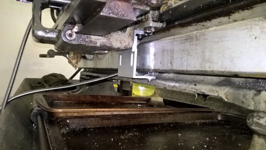
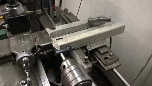
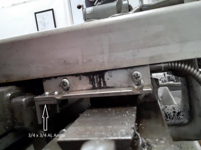
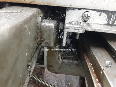
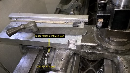
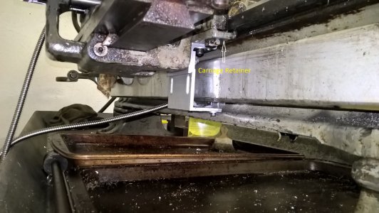
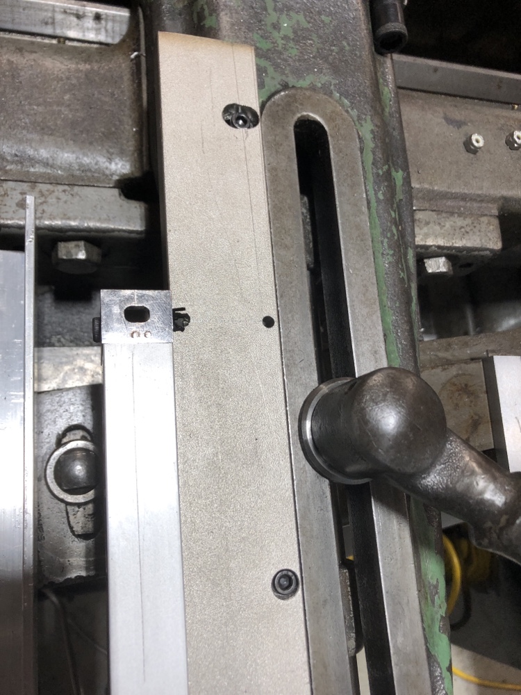
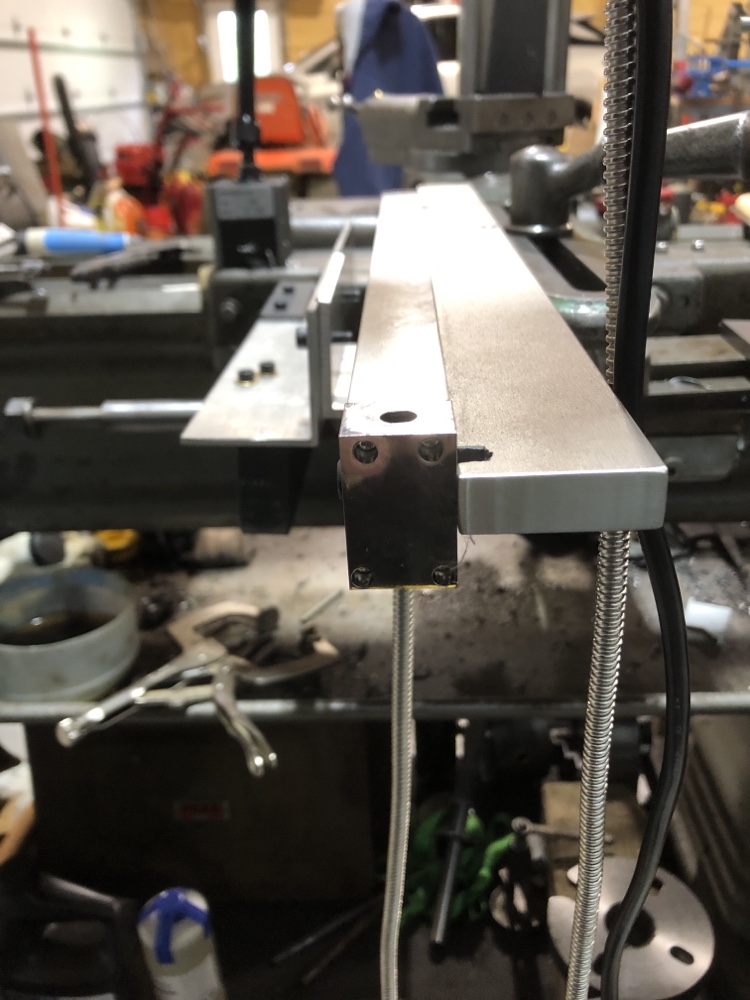
So I decided to bend up a piece of A36 flat bar (1/8 x 1-1/4) to make a hoop that the taper attachment can pass through, connected to an aluminum angle that gives it pretty good stiffness across the top. The hoop is screwed to the back of the carriage, and it hold the reader.

IMG_1505-dsqz.JPG


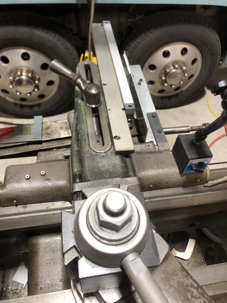
I tried about three different scale mounting schemes that were far too noodly until I remembered a couple of pieces of 1/2 x 1-1/2 stainless steel bar stock (hot-rolled 304) in the pile. It’s more than stiff enough. But what a pain to work with! I was able to drill and counterbore holes, one slotted, for 10-24 screws threaded into the taper attachment connecting bar, which positions the scale far enough back to avoid tailstock interference.

IMG_1500-dsqz.JPG


IMG_1502-dsqz.JPG


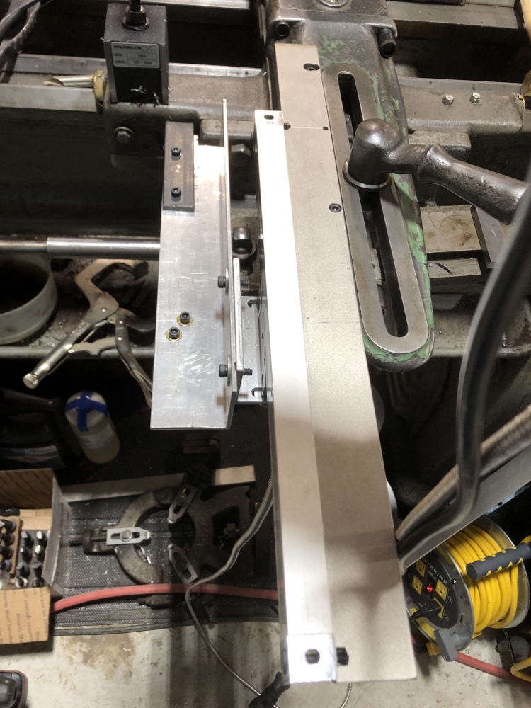
Tapping threads into the cast iron connecting bar was easy-peasy. Drilling and tapping 304 is the mother of all nightmares. I broke four drills and yes there is a hole with the shards of a tap in it that forced a slight repositioning of the scale. Horrible stuff that breaks cheap tools. But I bought a stock of US-made 4.2 mm drills from McMaster plus a a three-tap set of US-made metric 5x0.8 taps. Those worked to make the threaded holes I needed to anchor the scale using the supplied screws. So, there are the scars of mishaps but nothing that undermines rigidity or functionality.

IMG_1501-dsqz.JPG


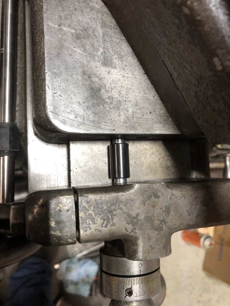
Adjusting the scale for minimum vertical runout exposed wear in my cross slide ways. I found the best average adjustment for the front half of the travel where the slide spends its time in turning operations. The slide travel on my 14-1/2” South Bend is 10” but a third of that puts the tool behind the spindle center—handy for the milling attachment but not for turning.

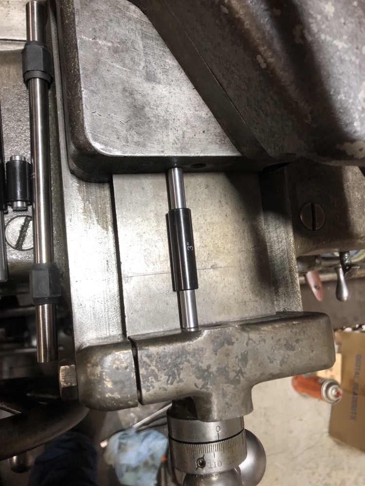
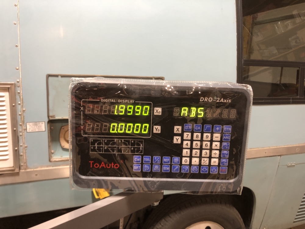
Calibration has been a tail-chasing exercise. No two inches of travel produce exactly the same readings. I used a thread stop on the cross slide dovetail as a measurement point after stoning a flat spot on it to use with micrometer standards. My gauge blocks were too difficult to line up consistently on the cast surface of the slide to read consistently. These disagree with the dial by 2-3 thou per inch, which is unacceptable. And my 2”-travel Mitutoyo dial indicator was worse than the screw dial. Mitu only claims 3 thou accuracy over two inches, but I don’t think mine is that good. I need to really inspect it on the surface plate. The micrometer standards ended up the best option for now.

IMG_1506-dsqz.JPG


IMG_1507-dsqz.JPG


But I’m at the point where 2” of travel in the usual turning range reads within a thou. Once it’s all done, I’ll recalibrate with turned stock that I’ve measured with a micrometer. Accuracy at the cutter is what counts.

IMG_1508-dsqz.JPG


With a mill I could have made prettier work of it to be sure. But I think what I have might work at least given the imperfections of a 78-year-old lathe.

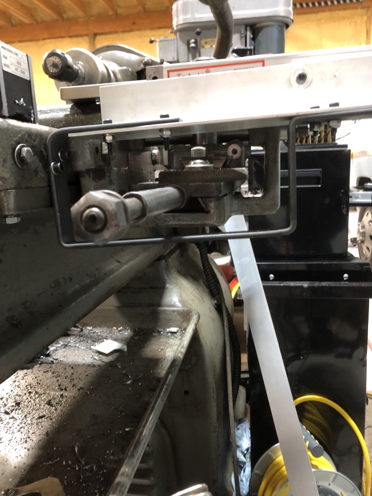
I mounted the DRO on the back of the rear-mounted switch box, which seems to be a good choice for now.

Rick “hoping the Z axis is easier” Denney
 
Last edited:
I think that looks pretty darn fine, well done! Especially working around the taper attachment too. Is it a trick of the camera or does that steel hoop that holds the read head tilt upwards away from the bed?

As for stainless, spin slow and feed hard with lots of cutting oil. Go up several drill sizes (I use the tap and drill chart from Little Machine Shop) or calculate the drill for 50% thread engagement. That will make your life considerably easier in stainless. The 5.2mm drill is for 70% thread engagement with M5x0.8. What you want for alu, way overkill for stainless and a bear to tap
 
Back
Top