- Joined
- Jun 28, 2021
- Messages
- 142
One thing about this airplane that did not work for me at all was the radio installation. The old KX145 nav/comm made it impossible for me to see the frequency numbers because they were hidden behind the knobs. The nav head was long gone and the panel was re-arranged so the EGT could be mounted in the panel instead of on a sub-panel. There was no transponder.
I had thought to maybe use some nice, new Garmin stuff mounted behind the front seat as is the norm for S-2 airplanes. That changed when I had a discussion with Ben M about the Trig products he installed in his S-2 and S-1T. The remote products would allow me to mount the controls right in front of my eyes -- no more looking down, past the stick, to see the radios! One thing I did want to try to do was to preserve the area where the sequence card would be placed. That area doesn't need to be the full height of the panel but it does need to be tall enough for an Intermediate free sequence card to fit. I doubt anyone flies Advanced in these airplanes anymore.....
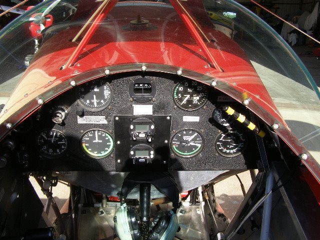
This is Ben's T model. The Trig heads are stacked vertically which would make it more difficult to use a sequence card in the center of the panel. But this made me wonder if I could mount them horizontally in the S-2A which would leave lots of room above them.
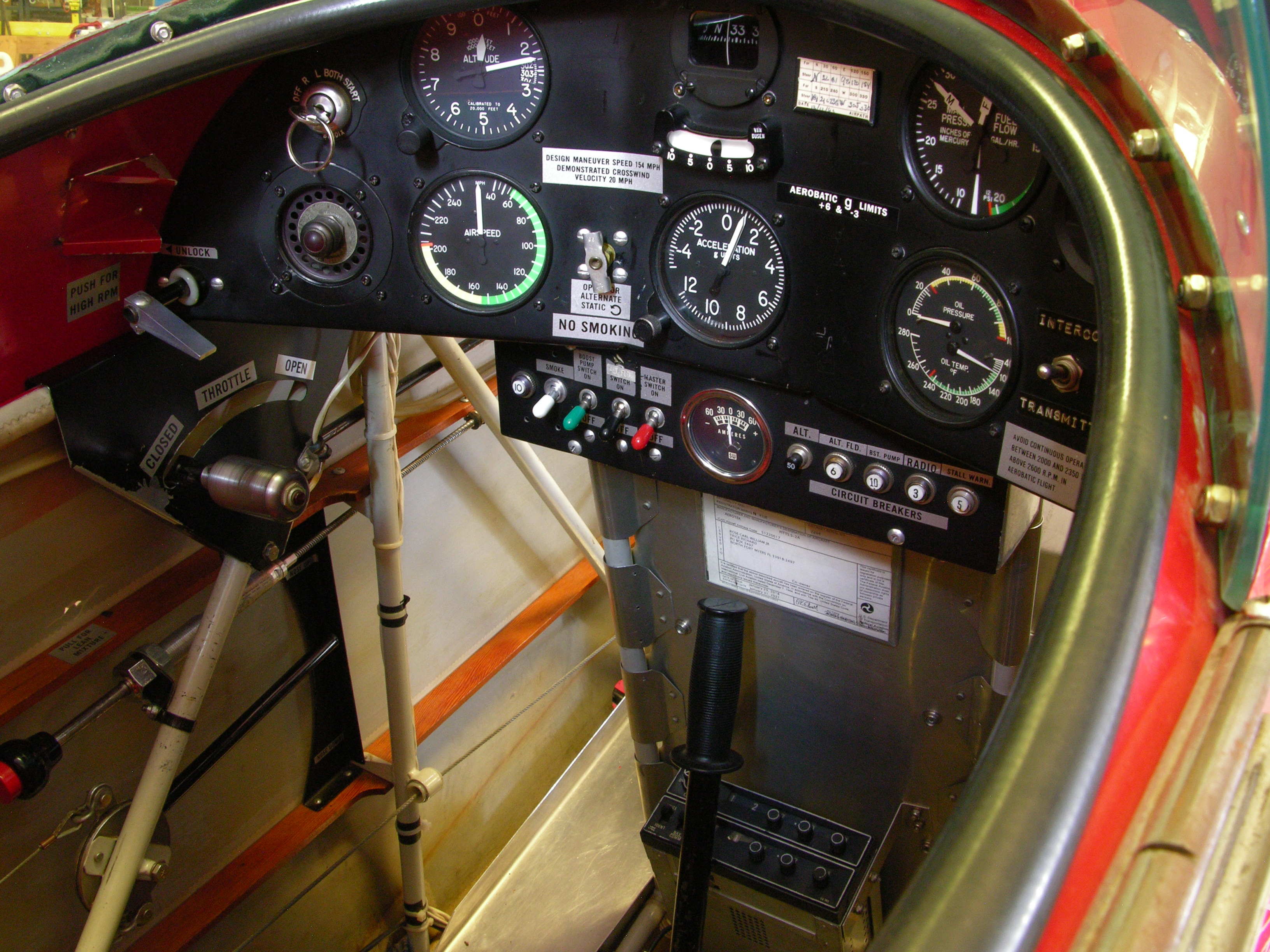
Pretty crowded panel in the S-2A. The G-meter would need to move and the hole for it would have to go away too. But the center part of the panel isn't wide enough for the two Trig heads to sit side-by-side.... And the stupid alternate static valve needs move and that set of holes will need to disappear. Time to lay it out in SWx and see what might be done.
This is what I settled on after trying a few options;
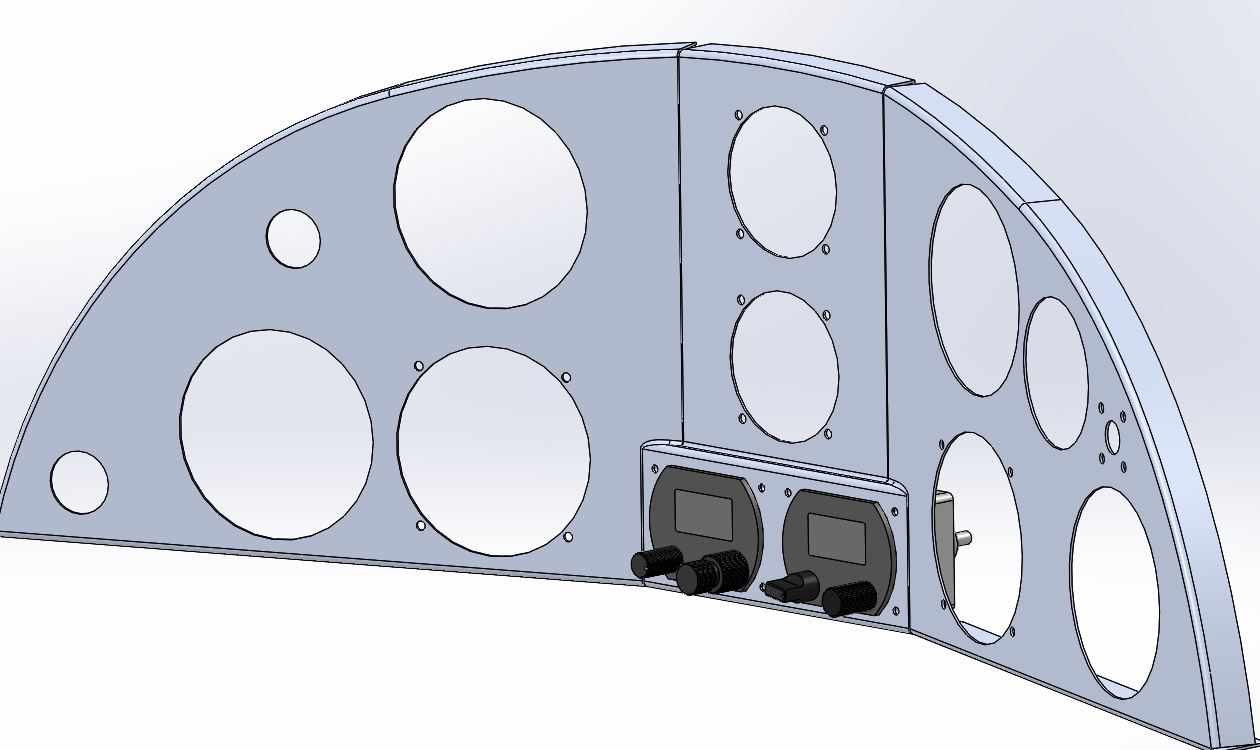
This was picked mainly because it looked better to my eyes than the recessed version below.
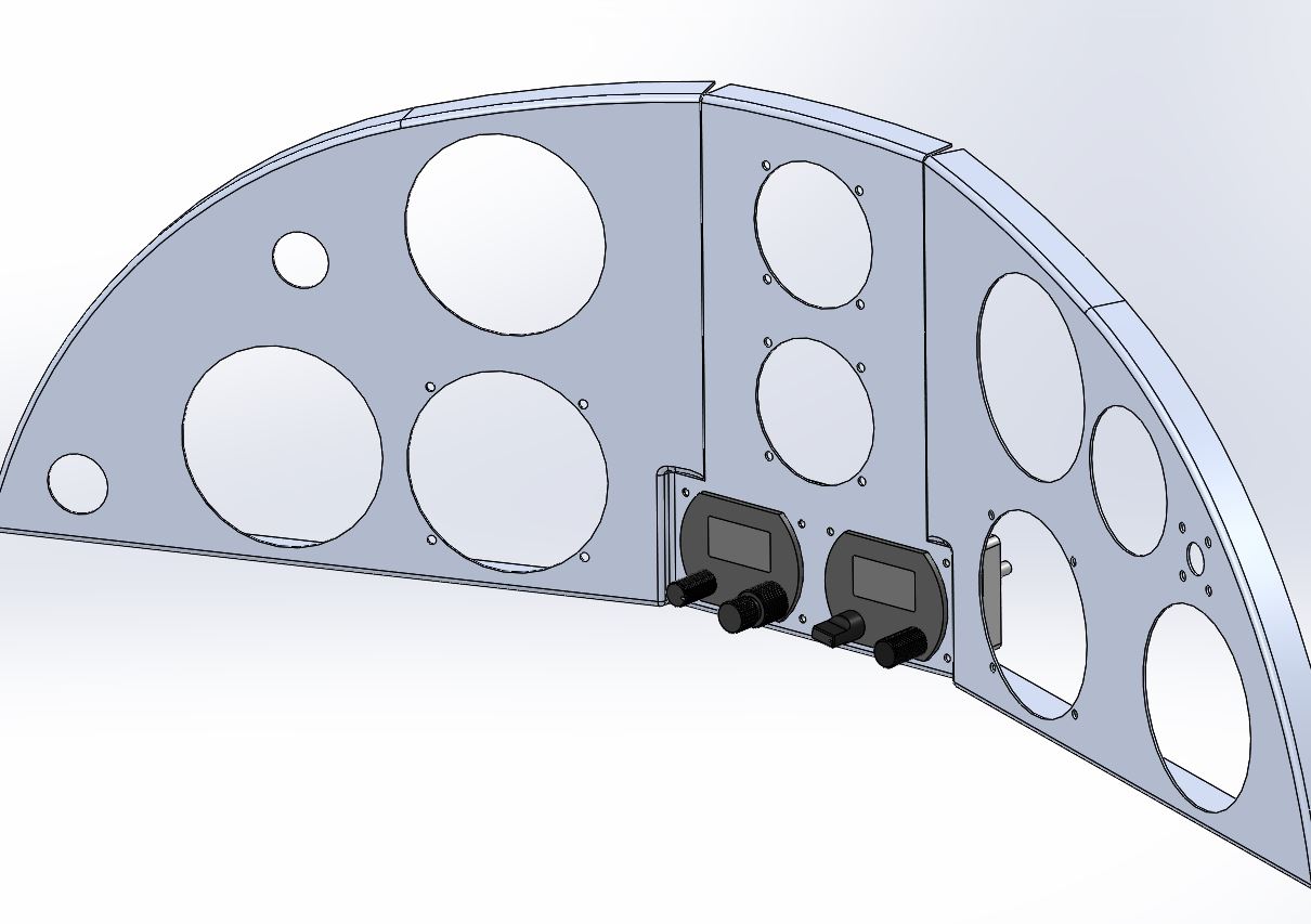
In both designs I made use of the space below the compass to add another 2-1/4" instrument hole. Either the EGT or the stall warning could go there and the spot where the old Nav readout was located could take the G-meter. I plan to move the alternate static valve over to the far right where it is out of the way.
There are a lot of ways to do most things, I had to pick one I thought I could pull off. The transitions at the upper corners of the new wide section of the panel could be sculpted from the welds or they could be formed into the original panel with a patch panel filling the old G-meter hole. That way, the patch panel could be a simple shape that would be easier to fit into its spot because the sides would be straight cuts.
Here's the plan, in SWx, showing the hammerform for the transitions and the patch panel cutout. The hammer form is made from the fine particle board with holes for clamping the instrument panel in place during forming. It will also serve as a fixture for doing the new holes in the milling machine.
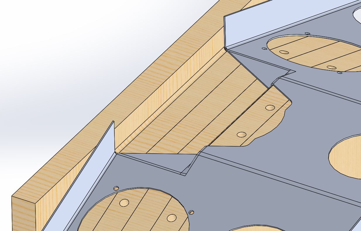
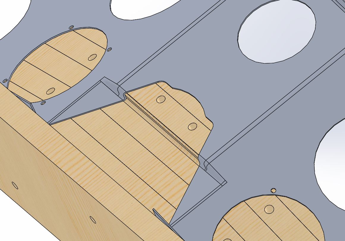
This is the patch panel, the only change I made was to eliminate the radiused corners -- sharp corners are easier to fit. The two holes in the patch panel's flange are the mount holes for the electrical junction box.
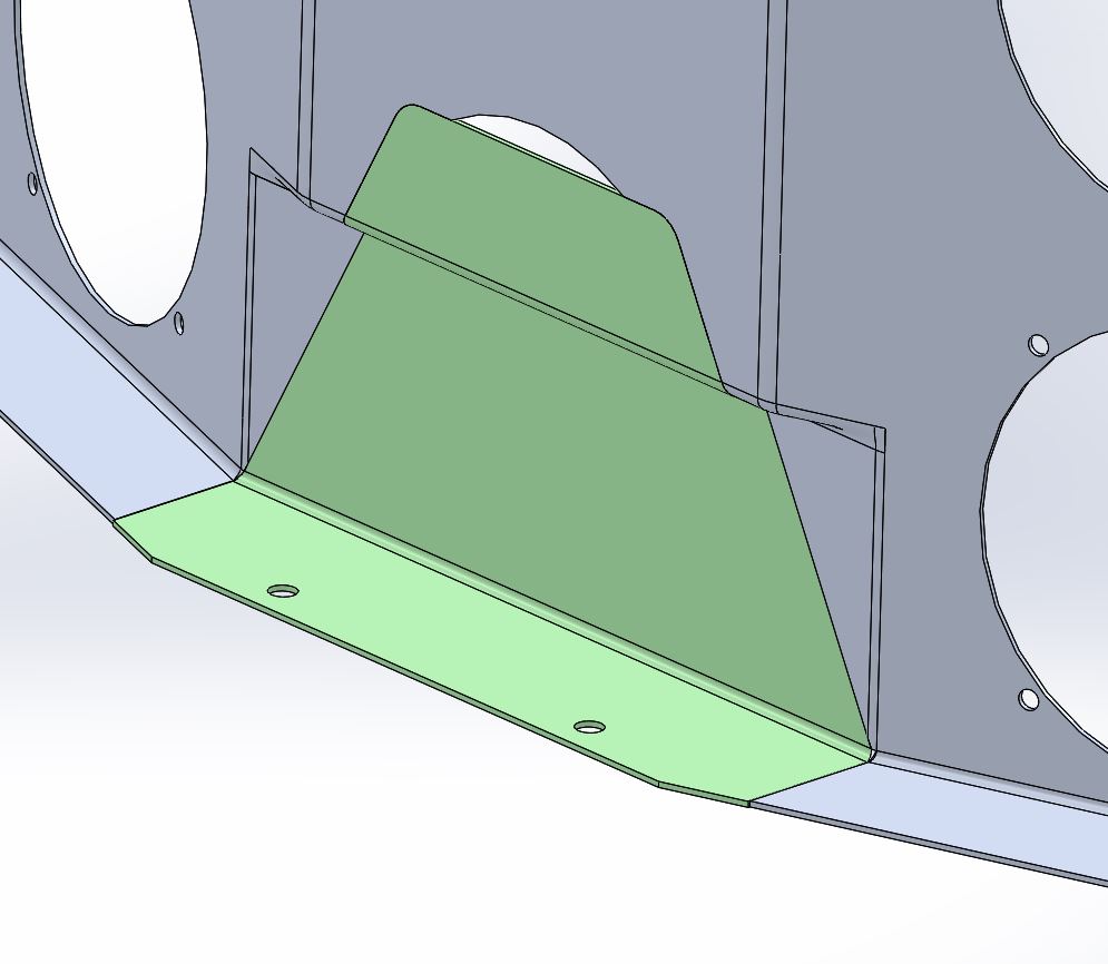
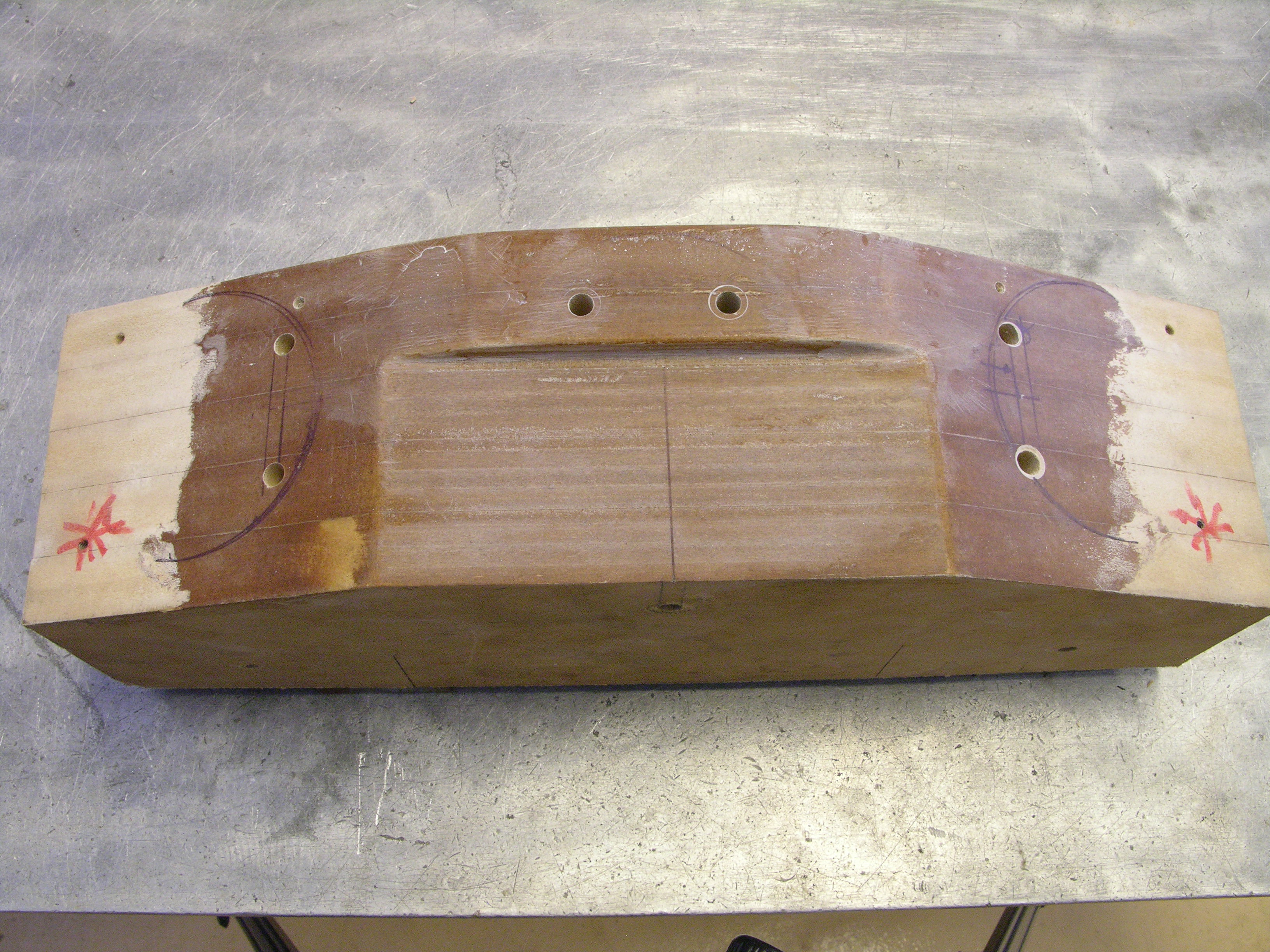
This is my hammerform. I use polyester resin to harden the surface but the tool has a limited life. There are holes for locating the instrument panel in a repeatable way and for clamping it in place.
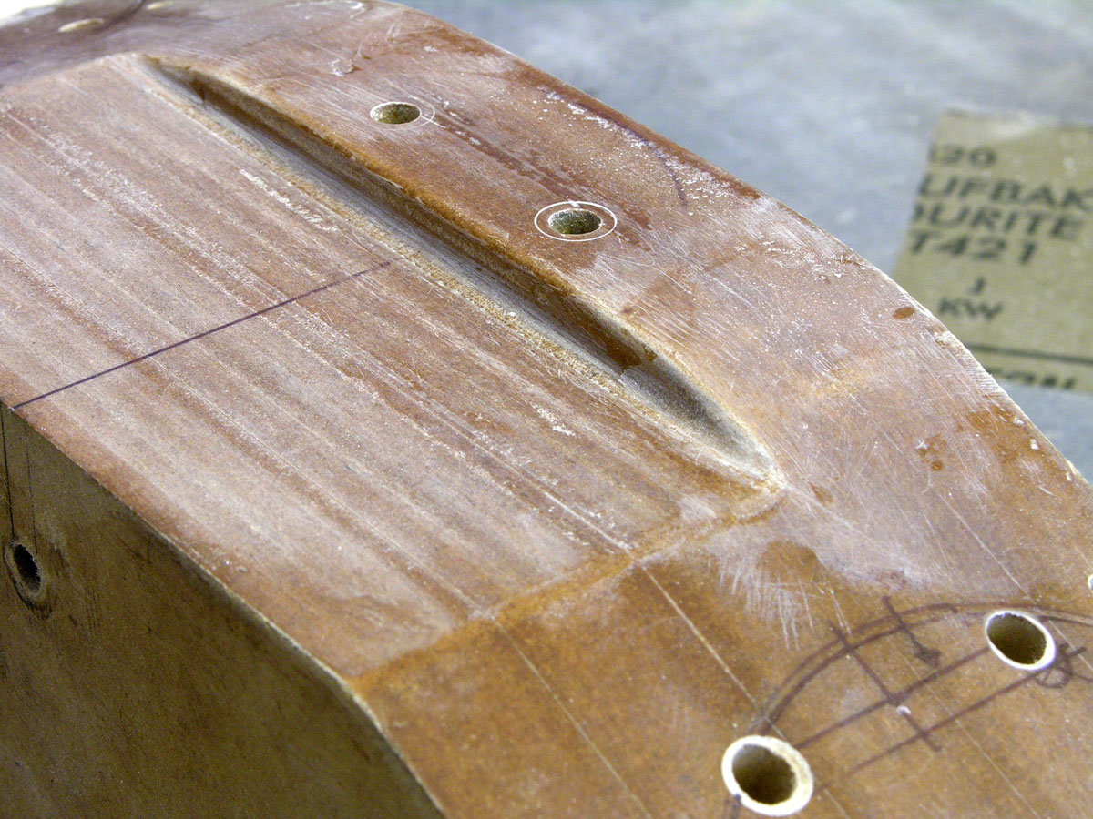
I had already used this for a few practice parts and it needed some repair.
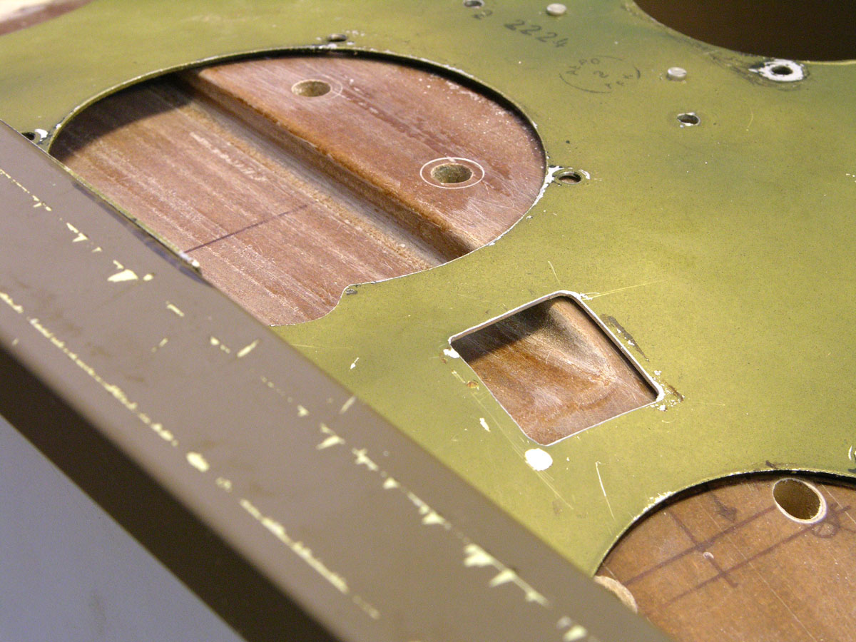
The panel laying on the form, roughly located. The original alt static valve location is ready to be patched.
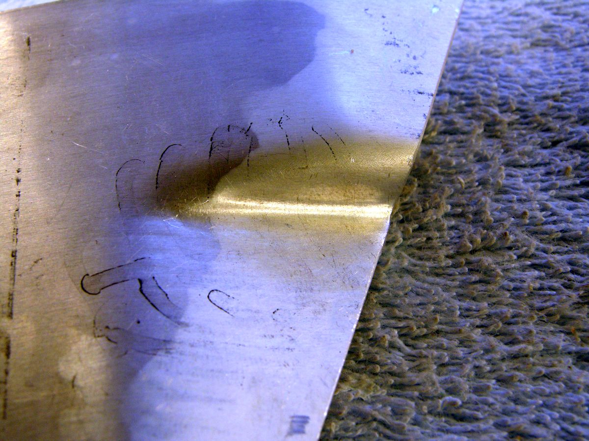
Practice part. Not too bad.
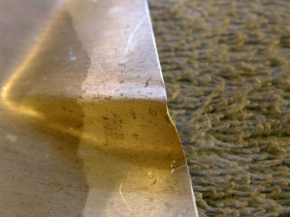
The back side. Looks OK, but....
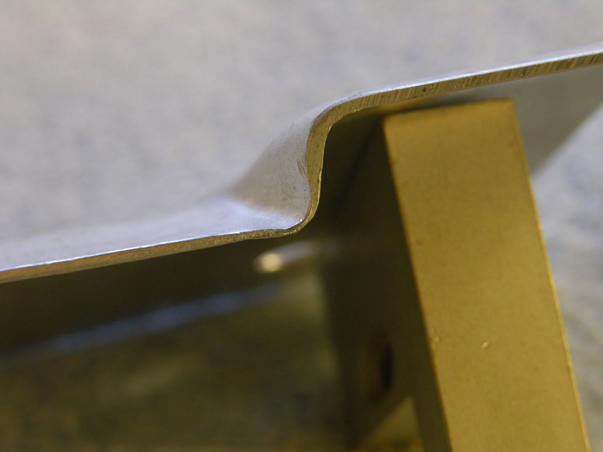
That's pretty thin! The factory panel is .040", as is this practice part. The thickness in that corner measures about .020". Gotta' be careful when welding in this area!
Here's a photo of the bottom side of the hammerform;
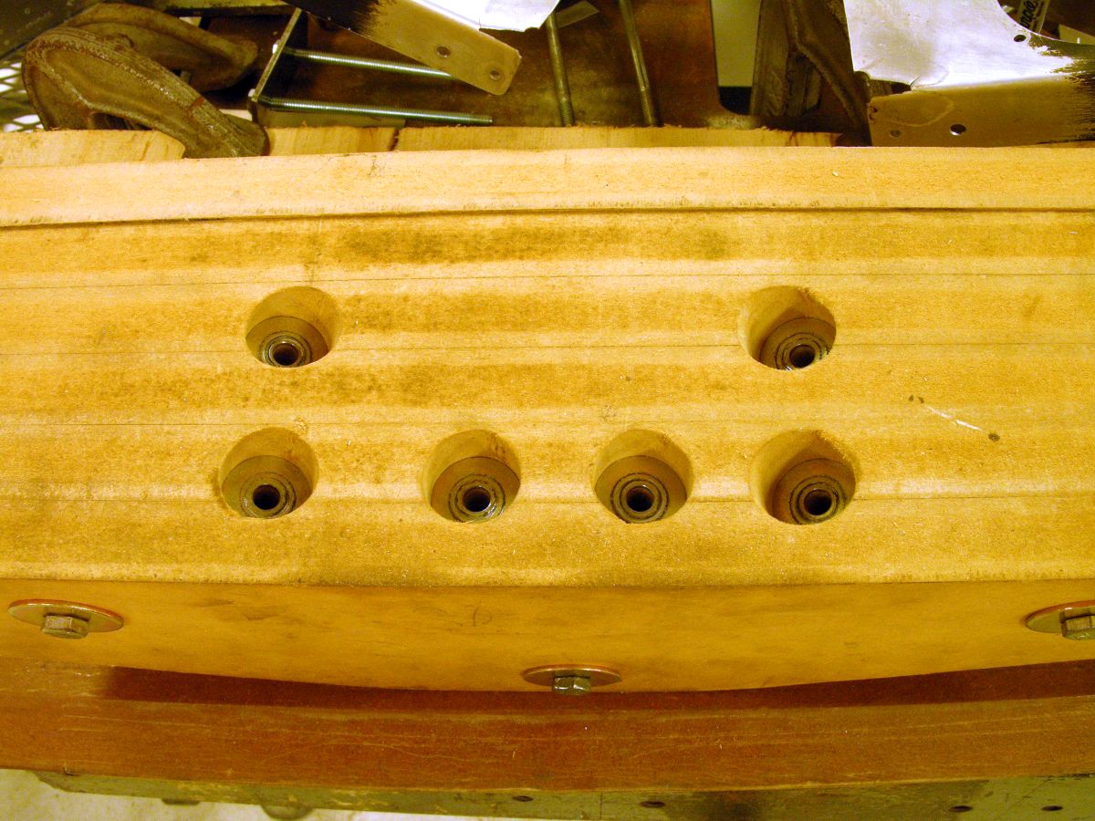
These are the holes for the clamp plates, they are all normal to the top surface. The washers are AN970-3 drilled out to 1/4" and stuffed into the counterbores.
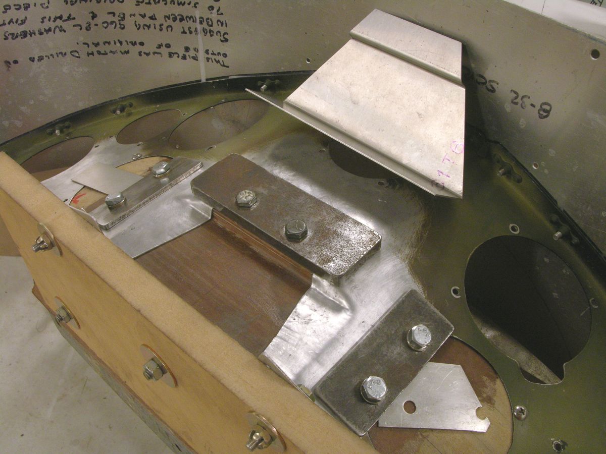
The forming of the transitions is in progress. I roughed out the patch panel hole, the finished hole gets carefully fit to the patch panel also shown here. It took 3-4 anneal cycles to get this fully formed.
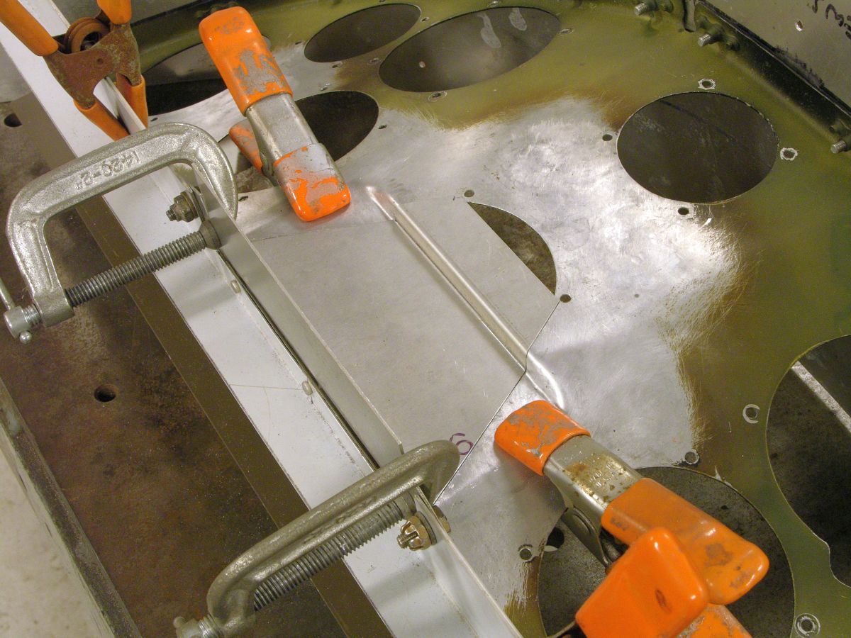
The patch panel is in place, pretty decent fit but took a while.
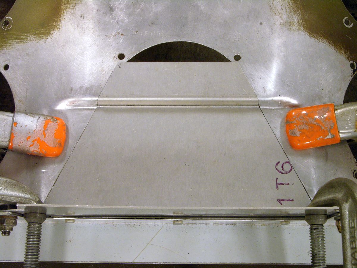
The area at the top was not patched since the new 2-1/4" hole will mostly consume the leftover from the 3-1/8" hole.
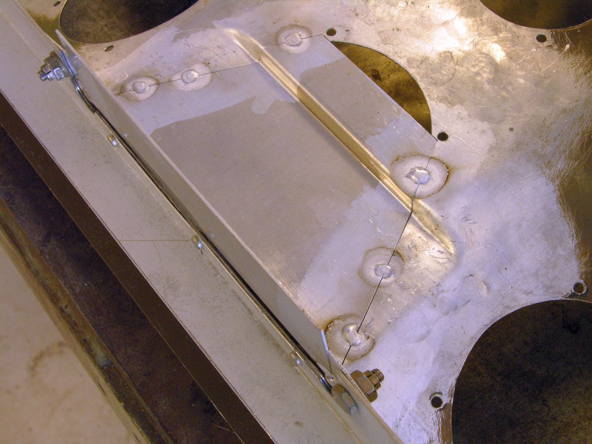
Time to start welding.
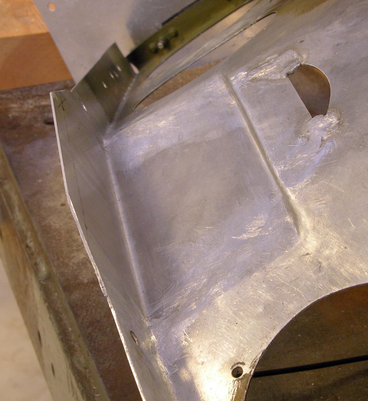
The welds are being dressed down. I had to use filler rod since this is 6061 which likes to crack if you don't use 4043 or 5356 rod. 1100 rod is NFG for this purpose.
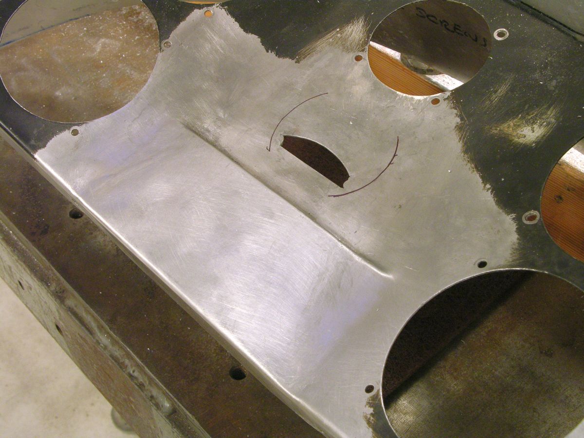
This is the pilot's side. I marked the new hole's approximate location just to convince myself there's was enough metal there.
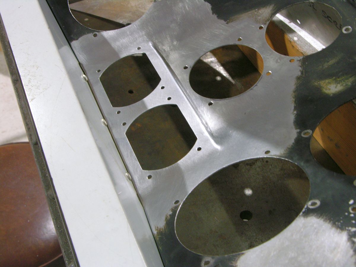
The holes were cut after fully dressing down the welds on both sides. I clamped the hammerform in the mill vice for that operation.
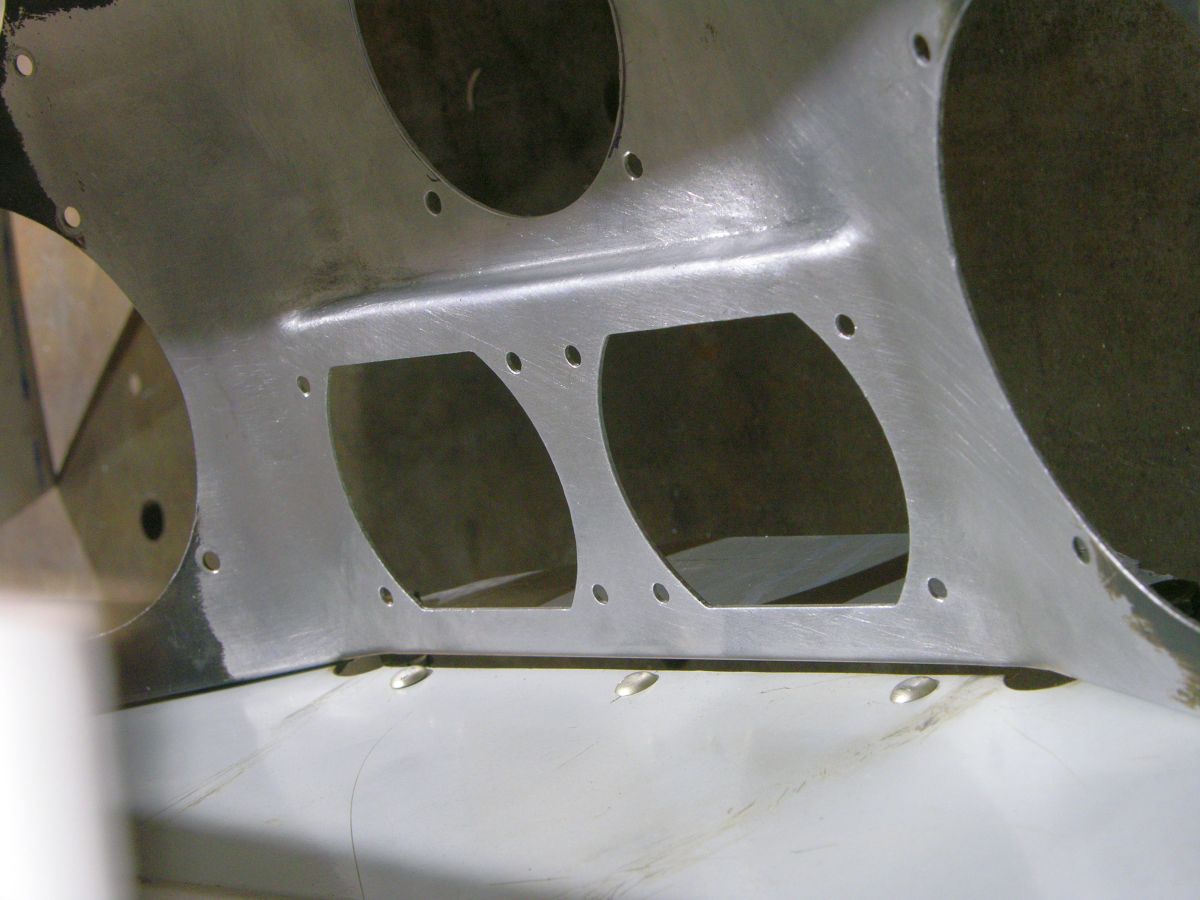
The important side. The transitions came out much better than they would have if I had welded in that area and tried to sculpt the welds into some sort of natural shape.
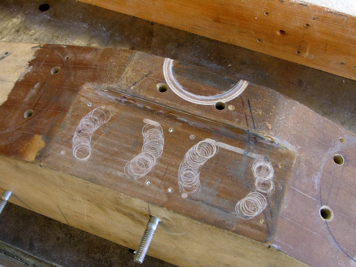
This is the well-used tool, ready for retirement.
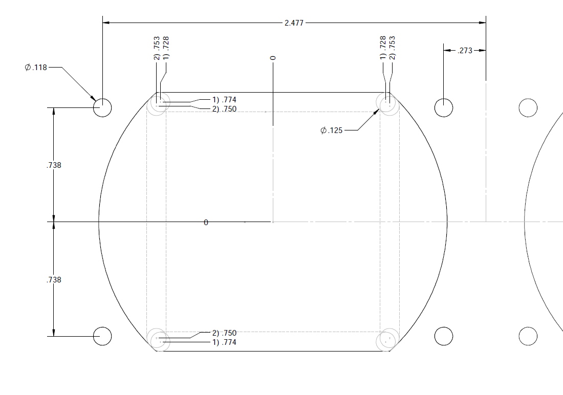
This is step one of the Trig cutouts, a 1/8" endmill in a rectangular path. The two locations right in the corner define that part of the curve much better than a 1/2" endmill could. The screw holes were drilled to .120" diameter. I guess Trig uses small screws.
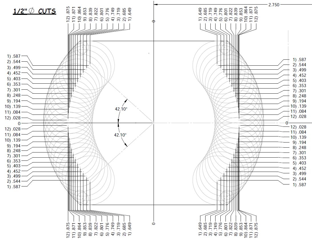
And now the fun begins. This was laid out in SWx, there are 24 cuts with a 1/2" cutter for each curve. 96 total cuts, 96 chances to screw up. I was very careful, only catching an impending mistake twice. The cuts are numbered and my final check before making any cut was to make sure the DRO on the mill showed a matched pair of numbers. I had two of these sheets printed and checked off each cut as I went along. A two-axis CNC kit for my mill would be a wonderful thing..............
There are about 26 little .002" bumps on each curve that Kim will need to smooth out. I could have just done more cuts,,,, NAH! Kim now has the instrument panel back, we hand delivered it last Friday. I wasn't about to ship this and hope for the best!
I had thought to maybe use some nice, new Garmin stuff mounted behind the front seat as is the norm for S-2 airplanes. That changed when I had a discussion with Ben M about the Trig products he installed in his S-2 and S-1T. The remote products would allow me to mount the controls right in front of my eyes -- no more looking down, past the stick, to see the radios! One thing I did want to try to do was to preserve the area where the sequence card would be placed. That area doesn't need to be the full height of the panel but it does need to be tall enough for an Intermediate free sequence card to fit. I doubt anyone flies Advanced in these airplanes anymore.....

This is Ben's T model. The Trig heads are stacked vertically which would make it more difficult to use a sequence card in the center of the panel. But this made me wonder if I could mount them horizontally in the S-2A which would leave lots of room above them.

Pretty crowded panel in the S-2A. The G-meter would need to move and the hole for it would have to go away too. But the center part of the panel isn't wide enough for the two Trig heads to sit side-by-side.... And the stupid alternate static valve needs move and that set of holes will need to disappear. Time to lay it out in SWx and see what might be done.
This is what I settled on after trying a few options;

This was picked mainly because it looked better to my eyes than the recessed version below.

In both designs I made use of the space below the compass to add another 2-1/4" instrument hole. Either the EGT or the stall warning could go there and the spot where the old Nav readout was located could take the G-meter. I plan to move the alternate static valve over to the far right where it is out of the way.
There are a lot of ways to do most things, I had to pick one I thought I could pull off. The transitions at the upper corners of the new wide section of the panel could be sculpted from the welds or they could be formed into the original panel with a patch panel filling the old G-meter hole. That way, the patch panel could be a simple shape that would be easier to fit into its spot because the sides would be straight cuts.
Here's the plan, in SWx, showing the hammerform for the transitions and the patch panel cutout. The hammer form is made from the fine particle board with holes for clamping the instrument panel in place during forming. It will also serve as a fixture for doing the new holes in the milling machine.
This is the patch panel, the only change I made was to eliminate the radiused corners -- sharp corners are easier to fit. The two holes in the patch panel's flange are the mount holes for the electrical junction box.
This is my hammerform. I use polyester resin to harden the surface but the tool has a limited life. There are holes for locating the instrument panel in a repeatable way and for clamping it in place.
I had already used this for a few practice parts and it needed some repair.
The panel laying on the form, roughly located. The original alt static valve location is ready to be patched.

Practice part. Not too bad.

The back side. Looks OK, but....

That's pretty thin! The factory panel is .040", as is this practice part. The thickness in that corner measures about .020". Gotta' be careful when welding in this area!
Here's a photo of the bottom side of the hammerform;

These are the holes for the clamp plates, they are all normal to the top surface. The washers are AN970-3 drilled out to 1/4" and stuffed into the counterbores.

The forming of the transitions is in progress. I roughed out the patch panel hole, the finished hole gets carefully fit to the patch panel also shown here. It took 3-4 anneal cycles to get this fully formed.

The patch panel is in place, pretty decent fit but took a while.

The area at the top was not patched since the new 2-1/4" hole will mostly consume the leftover from the 3-1/8" hole.

Time to start welding.

The welds are being dressed down. I had to use filler rod since this is 6061 which likes to crack if you don't use 4043 or 5356 rod. 1100 rod is NFG for this purpose.

This is the pilot's side. I marked the new hole's approximate location just to convince myself there's was enough metal there.

The holes were cut after fully dressing down the welds on both sides. I clamped the hammerform in the mill vice for that operation.

The important side. The transitions came out much better than they would have if I had welded in that area and tried to sculpt the welds into some sort of natural shape.

This is the well-used tool, ready for retirement.

This is step one of the Trig cutouts, a 1/8" endmill in a rectangular path. The two locations right in the corner define that part of the curve much better than a 1/2" endmill could. The screw holes were drilled to .120" diameter. I guess Trig uses small screws.

And now the fun begins. This was laid out in SWx, there are 24 cuts with a 1/2" cutter for each curve. 96 total cuts, 96 chances to screw up. I was very careful, only catching an impending mistake twice. The cuts are numbered and my final check before making any cut was to make sure the DRO on the mill showed a matched pair of numbers. I had two of these sheets printed and checked off each cut as I went along. A two-axis CNC kit for my mill would be a wonderful thing..............
There are about 26 little .002" bumps on each curve that Kim will need to smooth out. I could have just done more cuts,,,, NAH! Kim now has the instrument panel back, we hand delivered it last Friday. I wasn't about to ship this and hope for the best!
Last edited:

