PM1127VF-LB - Outboard Spider Nut Project

lpeedin

H-M Supporter - Gold Member
H-M Supporter Gold Member
Joined
Apr 22, 2014
Messages
479
Well, the new PM1127VF-LB has been more fun than I could have imagined. I got it all cleaned up and even broke down the cross slide and cleaned/ lubed / adjusted everything until it was to my liking.

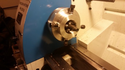
I decided that I needed to build a spider nut in hopes of eventually chambering a barrel, or even if I need to thread something really long that will need the support on the outboard side of the headstock.

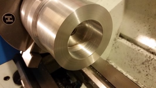
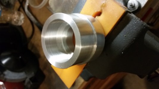
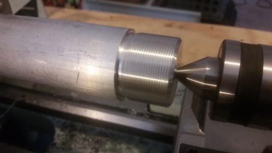
As best I can tell, the 'official' spindle thread pattern is 48mm x 1.5mm. I measured the OD of the existing and it is 1.875" = 47.625 mm. .375 mm = .015", so I figured that gives about .007" per side for flat tops on the threads. With this information, I took a piece of 2" aluminum round stock and turned a copy of the spindle. Then I checked it with the spindle nut and it actually fit!

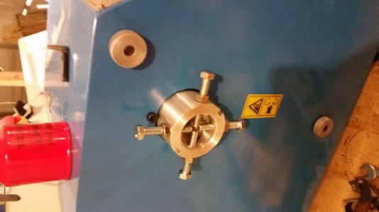
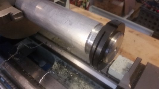
Next step was to turn the nut. I wanted it to fit through the side of the gear box cover so that I could run the lathe with the gear box cover in place. There is a nice 2.5" hole from the factory in the gear box cover that actually centered over the spindle hole. So, I turned a 2.400" OD for the nut, threaded the internal threads to have a minor diameter of 1.837", drilled and tapped (4) 5/16-18 holes, and then milled (2) notches for the spanner wrench. I am really happy with how it turned out. Tell me what you think. 20150117_130756 (1024x576).jpg20150117_131805 (1024x576).jpg20150117_210739 (1024x576).jpg20150117_210909 (1024x576).jpg20150118_003122 (1024x576).jpg20150118_182746 (1024x576).jpg
20150117_130756 (1024x576).jpg 20150117_131805 (1024x576).jpg 20150117_210739 (1024x576).jpg 20150117_210909 (1024x576).jpg 20150118_003122 (1024x576).jpg 20150118_182746 (1024x576).jpg
 
Looks good. Going to have to do one myself when my 1340GT finally arrives. Tough to do without the lathe at hand though...........
 
Nice job. Turned out great, glad to see you are enjoying your new lathe.
 
Very nice work!

I am also building a outboard spider right now, as part of a hand wheel collet closer project. I decided to make the spindle adapter without the internal threads, not so much due to laziness or fear, but rather to protect the spindle. My spindle is a bit different in that it has about 3/4" of unthreaded spindle at the far left end, beyond the threads. I am using four 1/8-27 NPS straight thread brass plugs to attach the smooth step bore adapter sleeve to the spindle. My thought is that if the work turns in the chuck I want the spider to also be able to turn on the spindle, protecting the spindle, which is more important than the work. The brass plugs will provide enough friction to put work in and out and to keep the adapter from falling off the spindle, but will allow it to spin on the spindle end if high torque is transmitted to the spider. That could be done on a spindle threaded to the end by making an internally threaded sleeve with a smooth O.D. for the spider to mount to, protecting the threads and spindle.

Anyway, be aware of that potential issue.
 
good work. I made one for the same reason. the metric threads were difficult for me, my machine has to be set with diff gears. took me a long time to get correct. also along the way, the half nut housing cracked.
but yours looks well done.
mike
 
Rather than start a new thread, I am going to continue with this one. I realized after making the spider nut that I the shortest barrels I could do with the side cover on and the 4 jaw chuck was approx. 19". The only solution was to eliminate the 4 jaw and make a spider chuck for the inboard side! In addition to that, I figured out how to bypass the side cover safety switch and the modified the outboard spider nut to have another set of holes just off the end of the spindle, giving me another 3/4".

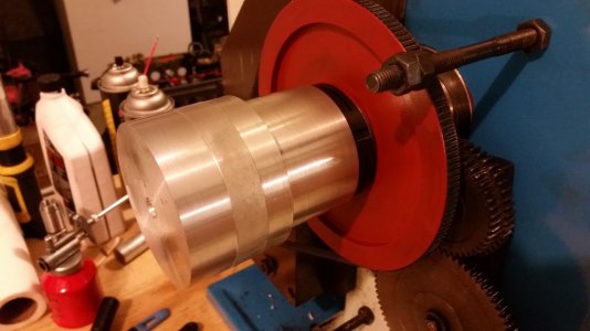
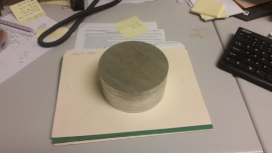
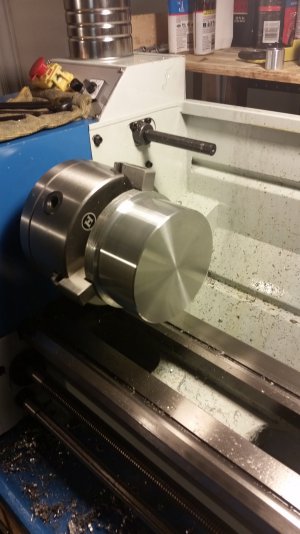
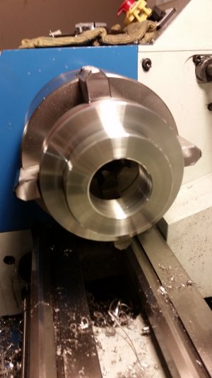
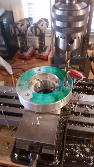
So, I went on Ebay and found a guy selling the perfect sized pieces of aluminum, 5.38" x 2.7" round stock. I ordered one up. I turned the OD to 5" just to have a nice round number. The actual OD of the spindle was 4.8xx" so the 5" looks nice on there. I left a 1" thick shoulder to allow good depth on my mounting studs. Then I turned the ID to 2" which will allow me to use the full 1.5" of clearance from the spindle bore and will account for the .200" thickness of the pads on the end of the 7/16-20 socket head cap screws that I planned to use. After I got the ID and OD where I wanted them, I marked the hole location by tracing alongside the jaws on the 4 jaw chuck. Then I put it in my mill and drilled and tapped the holes for the spider bolts.

Once I had all of that done, I needed to mark the locations for he mounting stud holes. I figured the easiest thing to do was to put the spider chuck on the spindle and then use a small punch inserted through the mounting holes to mark the back of the chuck. So I turned a small punch that would fit the mounting holes and short enough that it could be inserted from the back side of the spindle, between the spindle and the head stock. I used my trusty green marker on the back of the chuck, put the chuck on, and then use the small punch to make small marks for the holes. It worked very well.

I had an appopriate 10 x 1.25 tap on hand so I decided to turn my own mounting studs to that size, which was the same size as the mounting studs on both of my chucks that came with the lathe. I also had picked up some flange type nuts from the hardware store as I was tired of having to put on the washer, then the nut, everytime I changed chucks. It is easier to just use flange nuts.

All in all I think it turned out well. I could have done a little bit better job of getting my spider bolt holes absolutely perfect, but the small amount they are off doesn't hurt the centering process at all.

20150204_123025.jpg 20150204_204828.jpg 20150206_190355.jpg 20150208_143836.jpg 20150208_203144.jpg
 
Back
Top