Question on adding rake to single point gear cutters

tcooper27

Registered
Registered
Joined
Feb 2, 2023
Messages
44
Hi all,

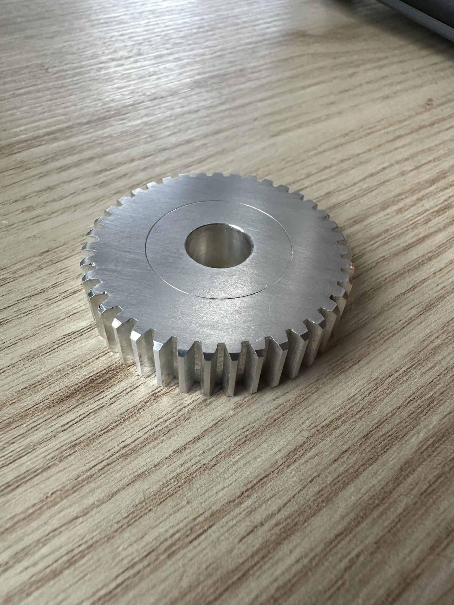
I'm hoping someone can help educate me on cutting geometry. I've been working on a project to make some change gears for my Emco V10p lathe and I used the button method to create a very respectable looking mod1 fly cutter out of some O1 and a holder that puts the cutter on its rotational center (as is normally recommended). It works really well and cuts some great looking gears. The problem I'm trying to solve now is when trying it out on aluminum the cuts were very jarring for my little mill. It looked and sounded much more like "slapping" than cutting.

The mill I'm using is the 4 speed geared head milling attachment for the V10p and I'm concerned about the abuse the fly cutter is putting on the phenolic gears so I've been looking for a way to reduce the cutting forces on harder materials. I came across this post by Mike about offsetting the cutter to create some rake and how it greatly reduced the cutting forces in steel. Here is Mike's illustration of the solution (my holder currently matches the example on the left):

1687457218146.png


Mike's post says the drawback to this offset is the cutter will create an elliptical cut in the gear. I'm new to the hobby and not an engineer so I'm having trouble wrapping my head around what he means about an elliptical cut and how this offset creates it. Furthermore I can't see how his solution of tilting the blank 5 degrees when creating the cutter counteracts that. Can anyone elaborate?

Another method I've come across is to tilt the blank 5 degrees in the vise and take a skim cut across the cutting face to create the rake angle. Does this introduce the same elliptical issue?

1687457552159.png1687457563347.png
 
You would be far better off if you bought/used form relieved gear cutters, you would get correct tooth shapes and faster feed rates and a great deal less jarring while cutting.
 
When the cutter is tilted the profile of its projection onto the work changes from circular to elliptical. There's been a very recent conversation here regarding machining grooves by tilting the mill column, to the effect that this produces an elliptical surface. For the same reason.
 
You would be far better off if you bought/used form relieved gear cutters, you would get correct tooth shapes and faster feed rates and a great deal less jarring while cutting.
Thanks, but I'm trying to avoid buying cutters right now. There's other tooling I'll use much more often that I'd rather get first. For the price of one cutter I got a chunk of O1 that will make 16 fly cutters and they only take about 20 minutes to make using a variation of the button method. I know the tooth shape isn't exactly the same profile as an off the shelf cutter but they still work well, it's just slow to cut and I wish it were a bit smoother.

eBYYfEr.jpg


When the cutter is tilted the profile of its projection onto the work changes from circular to elliptical. There's been a very recent conversation here regarding machining grooves by tilting the mill column, to the effect that this produces an elliptical surface. For the same reason.
I found that thread and read through it. That helped. Does Mike's suggestion of tilting the cutter blank when machining it to compensate for the elliptical cut make sense then?
 
Why don't you look at making some of the 4 tooth cutters like Clickspring does as you're already set up with button cutters to firm the profiles?

He's just released some great videos on the subject, and a calculator for setting up to make cutters:


Removing most of the material with a slitting saw before going in with the gear cutter isn't a bad idea either way.
 
I actually signed up for his patreon last night and watched his 4 tooth cutter video. Although I'm using the button method I'm using standard sized end mills as the "buttons", so each cutter just takes two quick cuts and I don't have to make any extra tools. There's a lot more time invested in making a circular cutter and he comments in the video that it's still very slow cutting. Maybe my expectations are just out of line.
 
Thanks, but I'm trying to avoid buying cutters right now. There's other tooling I'll use much more often that I'd rather get first. For the price of one cutter I got a chunk of O1 that will make 16 fly cutters and they only take about 20 minutes to make using a variation of the button method. I know the tooth shape isn't exactly the same profile as an off the shelf cutter but they still work well, it's just slow to cut and I wish it were a bit smoother.

eBYYfEr.jpg


I found that thread and read through it. That helped. Does Mike's suggestion of tilting the cutter blank when machining it to compensate for the elliptical cut make sense then?
If I'm reading Mike's post correctly, he's addressing the "elliptical cut problem" by using a special profile on the cutting tooth. The offset + tilt are there to provide some positive rake to reduce cutting forces, not to change the profile of the gear teeth.
 
"I found that thread and read through it. That helped. Does Mike's suggestion of tilting the cutter blank when machining it to compensate for the elliptical cut make sense then? "

Yes, That is the way to go, when you make the cutter, you do it at the 5 degree angle and then mount it at the same for cutting gears
I prefer a 7 degree angle for steel myself, but 5 works
I do not do Youtube as I can't stand the commercials but Mikes workshop is a good place for info.

Rich


Like Quote Reply

Report
 
A 4 tooth gear cutter doesn't change the cutting force needed to cut a gear. It only speeds up the cutting process.
A Module 1 gear cutter has a large cutting edge. That results in "large" cutting forces. Keep the stick out of the cutter as small as possible and reduce the cutting depth.
This is how I make my gear cutters and gears:
 
Following up on this to record what I actually did for future reference. I started with Huub's fly cutter method from his video but could not find an affordable set of cone drills that would cut cleanly and accurately. I ended up using the method described in this thread here which aims to use standard size end mills to create a set of cutters that cut a non-standard range of teeth instead of cone drills or precisely sized buttons that emulate off the shelf gear cutters that cut standard tooth ranges.

Gail in the linked thread provided a spreadsheet to do all the calculation work and I'll attach it here also for posterity. Gail posted directions for how to use it but the gist is you set the PA and DP and then play with the number of teeth until you find a button diameter that corresponds to a standard end mill (this is often a fractional tooth count so you just round up to the next whole tooth). You can then take the button spacing and button infeed numbers to make your fly cutter that will cut gears between the min and max number of teeth in the spreadsheet. Once you have your cutter you can then change the number of teeth in the spreadsheet to the gear you want to make and it will then give you the gear OD and the infeed depth for cutting the actual gear.

As an example the attached spreadsheet has the numbers I used to create a fly cutter for 47-104 tooth mod1 gears using a 5/8 end mill, which was then used to cut a 62 and a 69 tooth gear.
 

Attachments

  • 5500-GearCutters2.xlsx
    58.4 KB · Views: 3
Back
Top