- Joined
- Dec 9, 2021
- Messages
- 735
I bought one of the CME $299 specials, and the back plate is small, and likely too thin to use without adding a register for the adjusters. I haven't yet figured out what to do. I did some calculations, and I think I can get enough edge distance (1.5 times the major thread diameter from the hole centerline to the edge of the back plate) if I use 3/8" bolts instead of 10mm. That gives about the same "wall thickness" as a standard 3/8" nut if I reduce the bolt circle diameter by about 0.020. Using 10mm bolts, the wall thickness is less than 3/32".
I'm putting it on a 13x40 lathe, so the longer hang-out of the chuck design isn't as much of a problem.
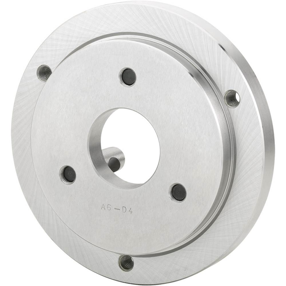
The back plate that is included is 6.346 in diameter and a little over an inch thick.
I'm putting it on a 13x40 lathe, so the longer hang-out of the chuck design isn't as much of a problem.
The back plate that is included is 6.346 in diameter and a little over an inch thick.