Restoring (hopefully) my new Smart and Brown SAB

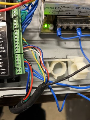
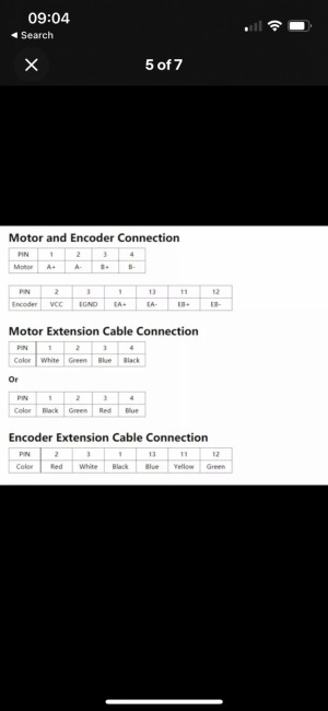
If I'm understanding the wiring for the stepper to driver correctly, I match the pin to colour from the tables at the bottom, then find the related pin in the tables at the top i.e. "Encoder Extension Cable Connection" table - Pin 2 is Red, find Pin 2 in the "Motor and Encoder Connection" table and find that it maps to VCC. Therefore the red wire goes in too VCC. Is this a correct way to do these mappings?
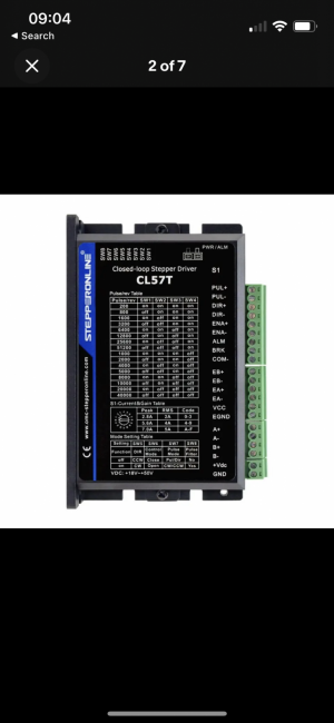
IMG_1894.PNG
IMG_1893.PNG
IMG_1891.jpg

This makes sense to me, but maybe I'm reading it totally wrong.
 

Attachments

  • IMG_1891.HEIC
    2.5 MB · Views: 1
You should be able to step the motor manually with a few jumpers. The Pul+ & Pul- connections and the Dir+ and Dir- connections are inputs to optoisolators. Connecting the - terminals to the negative of 5 volt power source and momentarilly touching the the Pul+ to the positive 5 volts should step the motor. A simple brush of the terminal will more than likely create a number of steps but you will hear the steps and if youplace a piece of tape on the shaft as Clough did, you will see rotation. connecting Dir+ to five volts should reverse the direction, verifying that the driver and stepper are working.
 
Just looking at the wiring pictures, I have a comment. Personally I wouldn't use the same color for + and - of any power supply. I see this on your +48V, and whatever you are using for the input of the stepper motor driver. You may have wired it right, but there is a big risk of getting it wrong. At the very least, make wire tags on the ends so if you have to rework things, bad things won't happen. Been fooled more times than I want to admit by stuff like that. Myself, I buy different colored wires. Makes it quick and easy to check things. Using the same color wires for twisted pairs makes it hard to know which is which without resorting to a volt ohm meter.

BTW, the stepper motor driver has a switch setting. You should set it to the +5V setting if you are using +5V logic, rather than +24V. Another thing to check is the current limit settings on the driver. Maybe the current setting is too low for the motor to move. I seem to remember my motor being rather weak at the minimum current setting. The motor would jump when stepped on the correct current setting due to the much greater torque developed.

I totally agree about using all of the same colour wire. The setup at the moment was just ‘bench testing’ and put together when I only had one colour of wire to hand. I’ve since ordered multiple colours of wire and will rewire it all when I fix it to its permanent enclosure.

The bigger news - it works! The 5V switch setting seemed to do it. Thank you so much! I was losing my mind with this.

So now on to fitting it all to the PC case as it’s final home and then mounting the stepper and encoder to the lathe. Any reason I shouldn’t mount the components to a piece of wood and then the wood in to the PC case? Seems that this would be easier then drilling holes in the PC case for all of the components?


Sent from my iPhone using Tapatalk
 
For my G0704, I just got an old computer case. Stripped the inside and used that for installing all parts… Worked well and cost me nothing…

View attachment 424626
View attachment 424627
View attachment 424628
I'm planning to do the same thing for a Taig 2019CR mill I'm building out to full CNC(with Centroid) . The original PC power supply will be useful for 5VDC and 12VDC. I'll add a 24VDC supply inside the case, along with a set of stepper drivers, etc. .... plus an additional fan, for improved cooling. Still need to find a compact PC to run the software and drive the monitor.
 
I’ve not had a lot of time to spend on the lathe over the last few months, but I do have a few updates, a few of which I’ve got info for with other posts I’ve made on the forum.

I’ll post them in seperate posts:


Sent from my iPhone using Tapatalk
 
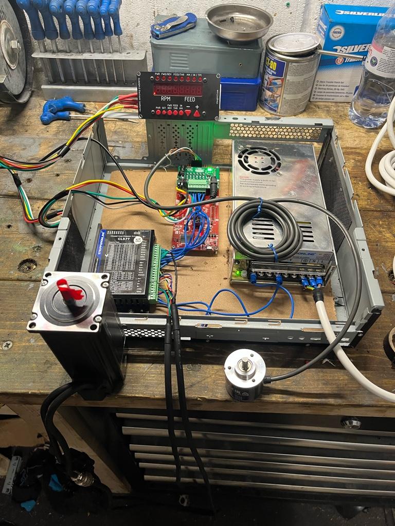
The ELS is slow progress as this is my first time with steppers/encoders/electronic soldering etc, but the wiring is done:

63d0392a47a14e497c4cc723afd3255e.jpg


I managed to break the Clough42 panel, so I’ve another one on order. It all seemed to be working before I broke the panel though. Next up is mounting the encoder and stepper.


Sent from my iPhone using Tapatalk
 
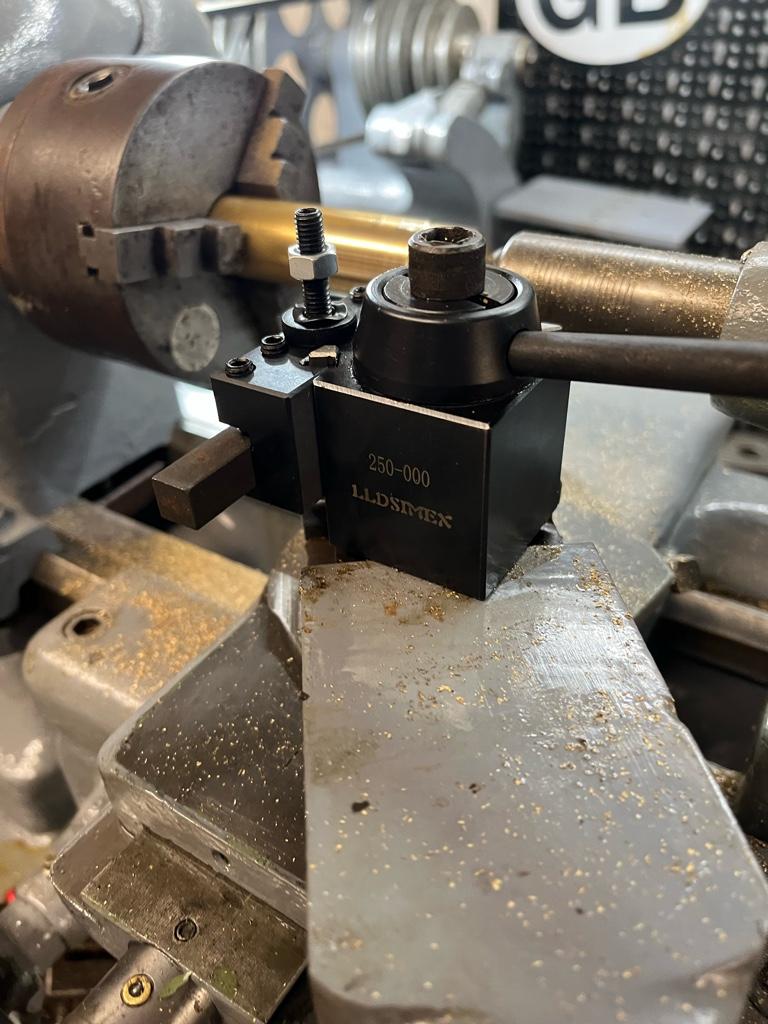
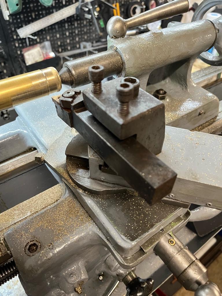
I’ve been asking about QCTP in another thread. I’ve an OXA:

76e1295ed1be360f22c742cc7c874da8.jpg


A Burnerd Type 2 Quick Set:

b6f9b4cc1a47cf404ff6782905880a15.jpg


And this (not sure what this is called):

e6e7732a12f1c6c5f4c0dd42a1dda95b.jpg


After some research, the OXA is too small for this lathe so is now on ebay.

The Burnerd is nice, but holds too small tooling and doesn’t have holders for parting, knurling and a few others. Not sure whether to sell this, if so I’ve no idea what it’s worth, or keep it as an ornament.

I’ve an AXA on order. Should be here soon.

The other tool holder I’ll keep as it holds 16mm tooling of which I have a fair bit that came with the lathe.


Sent from my iPhone using Tapatalk
 
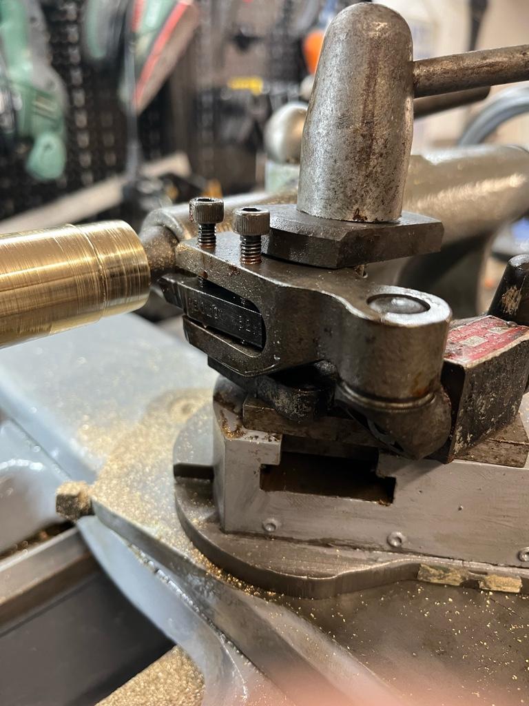
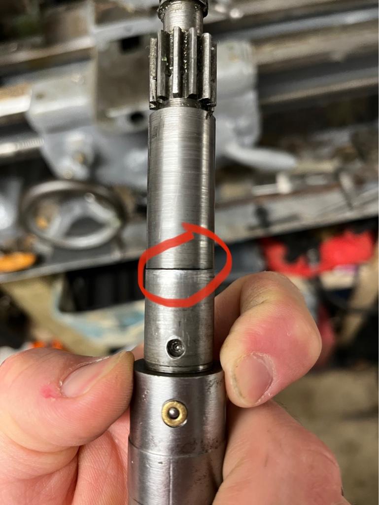
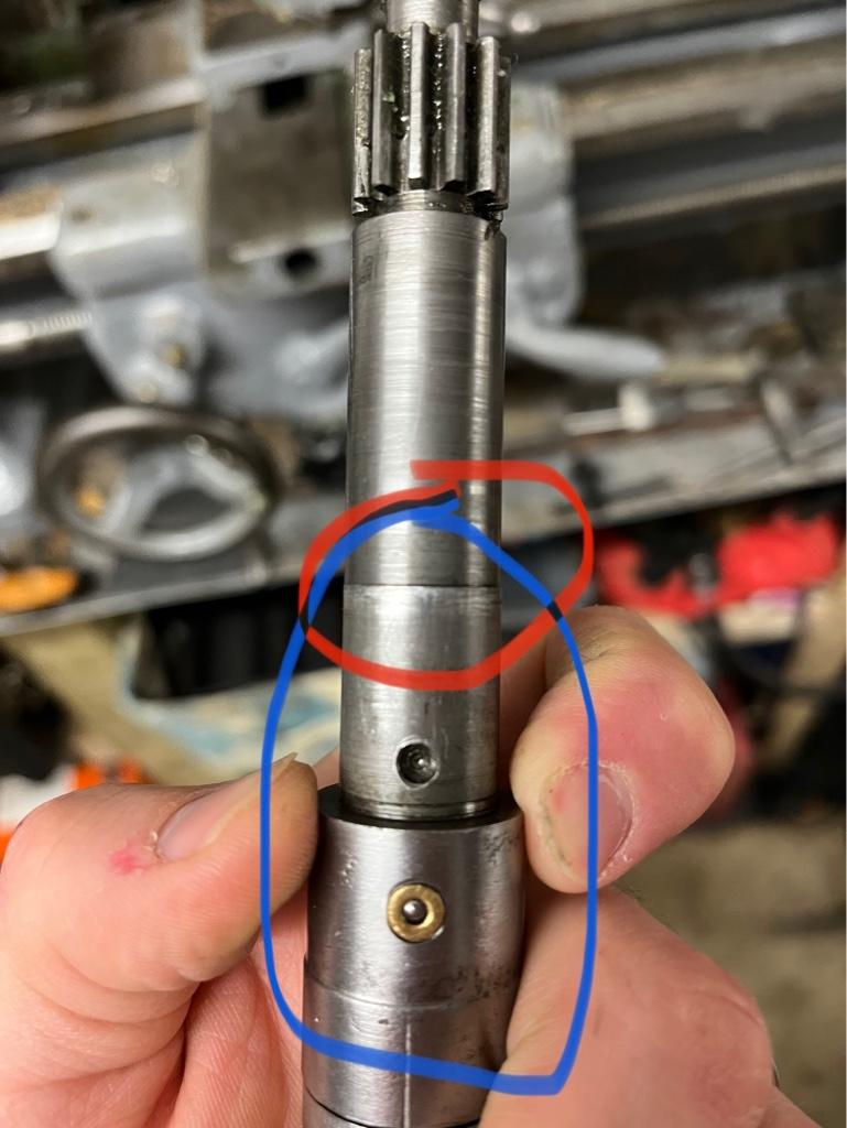
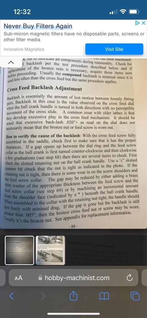
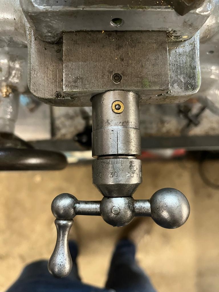
Next up was some play in the cross slide. I know that part of this was going to be because of the cross feed nut being worn, but it seemed worse than just that. I took it apart and found this:

c0a0ed1b6afc32fb0cf33819ebf6d9a2.jpg


ae9bb9443d7e739edb33f508c3570a7c.jpg


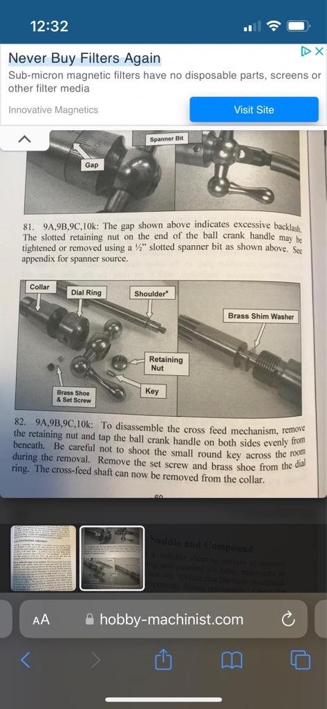
There was a gap that was opening up from the collar. This seems to be fairly common on south bend 9 and their clones:

d05ccb2809e8ac6c7cef2a73655ece8d.jpg


c0f9bcfce9f7cf83b925981405801032.jpg


The best fix is to get a brass washer to fit at the collar end, but as a quick hack I added a washer between the dial ring and the collar:

8758068930a5c2650f7559e49cd3778c.jpg


This will be a temp fix until I make the brass washer to add to the correct place


Sent from my iPhone using Tapatalk
 
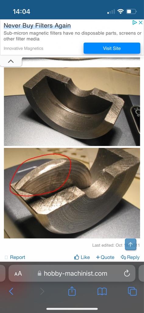
Lastly for now, I looked in to the power feed not working well. The engaegemt was terrible and as soon as the tool hit the work the power feed would basically stop. I took it apart and found that I’m missing the half moon shaped parts that go In the clutch. They look like this:

df0220eca3dcedfc0c2e347d99798d0a.jpg


I’m guessing someone has had this apart in the past and lost them. I’ve a separate thread to ask if someone can take some measurements of the half moon shaped parts so I can make some.


Sent from my iPhone using Tapatalk
 
Back
Top