RF-30 head-height crank, above worm gear or below?

bulgie

H-M Supporter - Silver Member
Joined
Dec 3, 2020
Messages
217
RF30 column height crank & gear.JPG

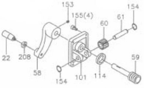
I just noticed I have mine assembled with the worm shaft #59 passing below shaft #61, whereas the drawing shows 59 passing above 61.
That is, I have the casting #101 upside-down. I can't seem to see any problem from having it that way, can you see any reason why it should matter?

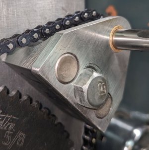
I would just flip the 101 casting over, except I'm making a power feed to replace the hand-crank, and it needs a steel plate bolted on top of plate 101, with a hole in the plate where the shaft 59 comes thru. I've already made and mounted the plate and I don't relish having to make a new hole. It's not just the 59 shaft that has to go thru my new plate, there's also a raised boss on the 101 casting. I made the hole 2" diameter to clear the casting by a wide margin. I can make a new 2" hole higher, to let me flip the 101 casting right-side-up, but the two holes will overlap like a figure-8 and it'll look stupid. Not the end of the world; my power feed looks pretty janky already anyway.

I will bite the bullet and make the new hole in my plate if there's a good reason to. Can you guys think of any reason why it would matter? Again it seems to work fine. I think I still get my full range of Z-travel, though I haven't tested that rigorously. Actually I just noticed it now, looking at pictures of my mill and other people's, plus the user manual.

Anyone else have theirs assembled like mine?
 
Can't see why it would matter- might affect the vertical travel a small amount at one end or the other
 
Thanks guys, I'll investigate further when I need to take that new plate off for some more hole making... See if I can find any difference between up and down, and report back. I know this is of earth-shattering importance. ;)
 
OK I took it apart, and it turns out it does matter. You have to turn the crank CCW to raise the head if it's upside-down like mine, vs. CW when assembled correctly. The following explanation is wordy and long and you can skip it unless interested.

The rotation direction matters, because the helix on the #59 shaft (drawing abov in post #1) makes the shaft want to push out, away from the column, when you turn it CW, so the "head" on the shaft is bearing against the back of the casting #101 when you crank it up. This is good, the right place for it to rub (though I might put a thrust bearing there to reduce friction).

When you crank it CCW to raise the head, the shaft is forced inward toward the column, and the rubbing happens between the crank handle #58 and outside of the 101 casting. Not fatal, but the only thing keeping the 59 shaft from going too far in is the little setscrew in the handle, which can slip. This has been working OK for me for the year I've used it since I first assembled it wrong, but I did notice that when the head is all the way down and you keep cranking (an unusual scenario I know), the shaft comes outward a pretty far distance, 4 mm or so, indicating how far in the shaft has migrated due to the setscrew slipping. Sub-optimal, though I can't think of any catastophic problem it might cause.

If the forces were symmetric this wouldn't matter, cranking one way or the other would put the rubbing force on the inside or the outside of the 101 casting, but the big weight you're pushing against means the forces are always in one direction whether you're raising or lowering the head. Either direction you move the head (or even at rest), the weight is always taking out the slack in the #59 shaft in the same direction, and we want that direction to be outward.

Let's just say assembling it right has a small and somewhat theoretical advantage, but there's no advantage to doing it wrong. Words to live by!

I have ordered a needle thrust bearing to go between the head of the 59 shaft and the back of the 101 casting. I'll let you know when it arrives, whether it fits in the space available (I think so) and whether it makes a noticeable difference in cranking effort. On mine (and probably all similar machines), the friction is noticeable. The effort to raise the head is borderline for my old shoulders, which both need surgery. Maybe most of that effort is just the work of raising the mass, but I feel like the friction is making a substantial addition to the force needed. (Yes everything is lubed, in case you were wondering...) Even when I get my power lift installed, it's just going to be driven by a little hand drill, probably one of my cordless ones if it has the horsepower. Pretty sure it will, because I'm gearing it down a lot with sprocket sizes — it's chain-driven. It'll go up/down slowly, but I'm not in a hurry.
 
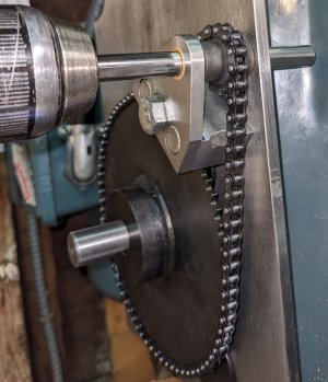
OK I got the power lift sorta mocked up, it works but needs bearings and more support. I might end up wishing I'd used a larger sprocket for the little one driven directly by the hand drill, for faster up-down movement. But like I said, I'm not in a hurry, and I like how low the forces are. My little cordless drill powers it up just fine, barely need to hold on with one hand.

Here's a 5-second video of it going up: (oops I deleted that video. There's a new one though, with the power-lift completed, see next post)
 
Last edited:
Here it is pretty much done.
8-second video of it going up:
Coupla pics:

z-lift.jpg

I'll cut that 3/8" drive shaft to length once I'm sure the design is finalized. Might cut the 18 mm driven shaft short too, but the extra isn't hurting anything, and it lets me go back to the hand-crank if I need to. (touch wood)

brace for the small sprocket.jpg

1/2" dowel pins are overkill but that's the only size I have on-hand, and 1/2" is the only reamer I currently own. It's definitely solid. Bronze oilite bearings for the drive shaft.

The chain and sprockets are industrial size #25, 1/4" pitch (half the pitch of bicycle chain). 1/6 gear ratio (12 to 72 tooth), seems about right. Forces involved are very low, easy one-hand operation, goes fast enough for me.

This is inspired by the design from the youtuber who goes by "Winky's Workshop", though I changed a few things. Thanks Winky!

I will be using the backplate of this thing as part of an anti-rotation attachment, you know to keep the X and Y when you raise the head. Like Winky's only heavier/stiffer. Should keep your head position more precisely than his did, too much flex in his.
 
Last edited:
Back
Top