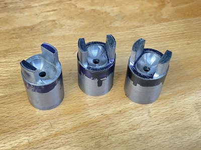
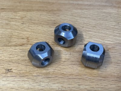
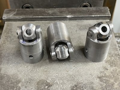
We don't know what these are called and since they haven't worked in recent history, the function is not yet fully understood. They have something to do with either the elevation sight trim or motion limits on the 5 inch/51 caliber secondary guns on the battleship. We did know that major repairs were needed. First is one straight off of the gun during disassembly. The big wedge was rusted into the large casting but once it was out the screw came out of the wedge easily. That really surprised me. 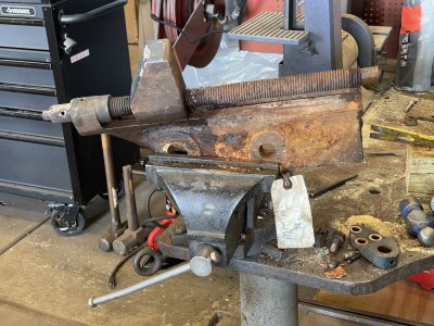
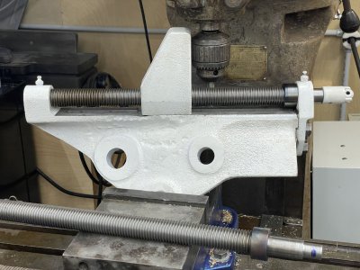
The one that's primed in white is fully repaired.
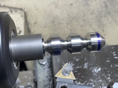
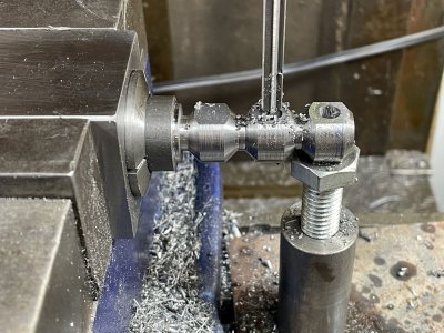
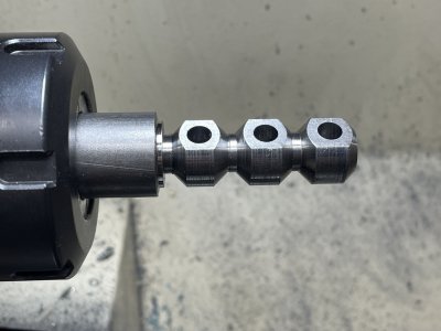
The screws all had to be replaced. They're 1-1/8 x 7 left hand threads. After a lot of searching one of the employees found some 36" all thread in the right thread for a measly $200/stick. Three sticks were needed. The larger diameter feature was part of the screw on the originals. I made these .0015" undersized on the ID, heated them with a propane torch and let them shrink onto the area that I had cut down for the purpose. Each screw had to be cross drilled at a precise location at the blue mark on the right end.
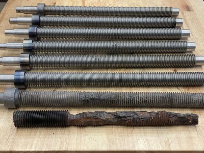
These are the six completed screws and part of an original. I expected this one to be rusted solidly into the wedge but like the others is unscrewed easily. The work was cone on a Grizzly G9972Z which only has a little over 1" bore so all of the work had to be done with a steady rest. It was very time consuming to constantly have to reset the steady rest and re-measure from the reference surface.

The one that's primed in white is fully repaired.

The screws all had to be replaced. They're 1-1/8 x 7 left hand threads. After a lot of searching one of the employees found some 36" all thread in the right thread for a measly $200/stick. Three sticks were needed. The larger diameter feature was part of the screw on the originals. I made these .0015" undersized on the ID, heated them with a propane torch and let them shrink onto the area that I had cut down for the purpose. Each screw had to be cross drilled at a precise location at the blue mark on the right end.

These are the six completed screws and part of an original. I expected this one to be rusted solidly into the wedge but like the others is unscrewed easily. The work was cone on a Grizzly G9972Z which only has a little over 1" bore so all of the work had to be done with a steady rest. It was very time consuming to constantly have to reset the steady rest and re-measure from the reference surface.


