

- Joined
- Feb 8, 2014
- Messages
- 11,145
I have been asked to build semi-automatic parts weighing/counting machine for a customer. We decided to make it rotary to save space, and have a two tier rotor system, top to store bulk parts, bottom to store kitted parts. An operator will select the order on the computer screen and physically move the parts from the bulk bin into the weighing/counting hopper, then release the parts into the kitting bin. Each time the parts are released, the bulk parts (top) rotor will rotate to the next part in the kit. When the kit is complete, the lower bin will index to the next station and the process begins again. From this machine, the kitted parts will go to the existing bagging/printer for final packaging.
A concept overview, just to put this in perspective, the lower rotor is 28'' diameter. The numbers and letters will correspond to part locations that will be programmed into the system.

So how do you do the machine work on a 28'' diameter ring when your machine only has 14'' of Y axis travel? Drilling mount holes, milling bin pockets, engraving letters & numbers, accurately machining the ring gear pocket.
Time to dust off the rotary table.
Some time ago I converted my 6 inch Vertex Super Spacer to a rotary (4th) axis for another project. See that project here: https://www.hobby-machinist.com/threads/4th-axis-build.40642/#post-348948

I need to mount a table on it in place of the chuck. So this is the 12 inch table that will bolt on in place of the chuck. This will be made from 3/4 inch MIC6 aluminum tooling plate. I need to dig that out in the morning, need to move some stuff around in the shop to get to it with the forklift.

But I have a little clearance problem, it was designed to take a 6 inch table, but I want to use a 12 inch table to better support my 28 inch rings. The mounting foot sticks up about 1.25 inches above the mounting surface.

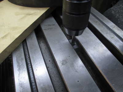
I had a couple of options, build a riser to put the table above the mounting foot, or simply trim the mounting foot. After some thought and testing some alternate clamping methods, I decided to trim the foot. It won't affect the horizontal operation, and I can still properly clamp the unit to the table. Tape over the various holes to keep the cast iron chips out of the works.
1/2'' roughing end mill, 0.600 DOC, 120 FPM (900 RPM), 0.375 stepover, 7 IPM feed.

So for the moment, the next order of business is to rough out the rounds. Two 28 inch, one for the lower rotor and one for the spoil board, and one 27 inch for the upper rotor.
First I had to make a trammel point to be able to swing the circle with a Sharpie. Some 1/4'' SS rod, and a couple of other small scraps and a few minutes on the lathe and presto..... instant (almost) Sharpie trammel point. The Sharpie is a light press fit into its holder.

And we have a circle. The large parts of this project are made from 3/4 MDF. Nice stuff to work with. The local lumber supply has a panel saw, so I had them slice the two full sheets of MDF into my rough sizes, $0.50 / cut and worth every penny so I didn't have to handle full sheets.

Then over to the band saw for roughing out the circle.

And 3 rounds cut

This is how they will fit on the mill, had to move the ram out a bit from its normal position. This gives me a Y work envelope that is about 6 inches wide, plenty of room.

That's all for tonight folks, stay tuned for more.....
.
A concept overview, just to put this in perspective, the lower rotor is 28'' diameter. The numbers and letters will correspond to part locations that will be programmed into the system.
So how do you do the machine work on a 28'' diameter ring when your machine only has 14'' of Y axis travel? Drilling mount holes, milling bin pockets, engraving letters & numbers, accurately machining the ring gear pocket.
Time to dust off the rotary table.
Some time ago I converted my 6 inch Vertex Super Spacer to a rotary (4th) axis for another project. See that project here: https://www.hobby-machinist.com/threads/4th-axis-build.40642/#post-348948
I need to mount a table on it in place of the chuck. So this is the 12 inch table that will bolt on in place of the chuck. This will be made from 3/4 inch MIC6 aluminum tooling plate. I need to dig that out in the morning, need to move some stuff around in the shop to get to it with the forklift.
But I have a little clearance problem, it was designed to take a 6 inch table, but I want to use a 12 inch table to better support my 28 inch rings. The mounting foot sticks up about 1.25 inches above the mounting surface.
I had a couple of options, build a riser to put the table above the mounting foot, or simply trim the mounting foot. After some thought and testing some alternate clamping methods, I decided to trim the foot. It won't affect the horizontal operation, and I can still properly clamp the unit to the table. Tape over the various holes to keep the cast iron chips out of the works.
1/2'' roughing end mill, 0.600 DOC, 120 FPM (900 RPM), 0.375 stepover, 7 IPM feed.
So for the moment, the next order of business is to rough out the rounds. Two 28 inch, one for the lower rotor and one for the spoil board, and one 27 inch for the upper rotor.
First I had to make a trammel point to be able to swing the circle with a Sharpie. Some 1/4'' SS rod, and a couple of other small scraps and a few minutes on the lathe and presto..... instant (almost) Sharpie trammel point. The Sharpie is a light press fit into its holder.
And we have a circle. The large parts of this project are made from 3/4 MDF. Nice stuff to work with. The local lumber supply has a panel saw, so I had them slice the two full sheets of MDF into my rough sizes, $0.50 / cut and worth every penny so I didn't have to handle full sheets.
Then over to the band saw for roughing out the circle.
And 3 rounds cut
This is how they will fit on the mill, had to move the ram out a bit from its normal position. This gives me a Y work envelope that is about 6 inches wide, plenty of room.
That's all for tonight folks, stay tuned for more.....
.
Last edited:


 to get through the plate it took all of the tap so running it down until the last thread of the tap was at the top of the hole before hitting reverse. I ran it pretty slow. There was no way I was going to hand tap all of those holes.


 That's the nice thing about being retired, if I don't feel like doing something today, it will just wait until I do feel like it.

 I chose them for the ID, needs to fit the 2'' center support tube.


