Servo 150 Power Feed Circuit Board Connectors and Schematic

ckiernan

Registered
Registered
Joined
Dec 31, 2017
Messages
4
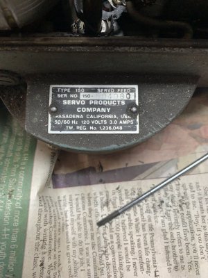
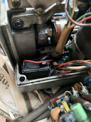
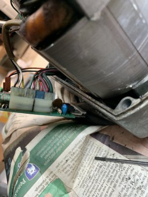
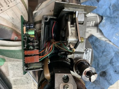
Hi, the Servo 150 Power Feed on my new acquired Series 1 Bridgeport started acting up and I noticed the power switch/circuit breaker was loose and kept pushing into the unit. I took it apart and found that the retaining nut was threaded on the inside of the unit (wondering if someone else took this apart and forgot to put it on the outside of the switch). I tried to keep the connectors organized but when I put it back together it keeps tripping the circuit breaker. I also found a ceramic disk capacitor broken of the board that I think goes across pins 2 and 4 of the heavier connectors if you count from the top down. Does anyone have any information on where these connectors belong or a schematic for this unit?
Appreciate any help, Thanks in advance,
-Carey
 
Last edited:
Take the unit apart again and look for burn marks around the power switch/breaker- post a picture if possible
Often switches will have both a nut inside and a nut outside to space the unit a certain distance from the panel
Don't worry about the ceramic disc, it's function is probably trivial noise suppression
 
Thanks for getting back to me. There doesn't seem to be enough thread on the switch to hold a second nut (might have broken off. Here's some pics of the connections as you requested. I'm not sure about whether I have the proper connectors in the right locations which is why I was looking for a schematic diagram. Appreciate any help you can offer
 

Attachments

  • IMG_0070.jpg
    IMG_0070.jpg
    288.3 KB · Views: 8
  • IMG_0071.jpg
    IMG_0071.jpg
    223 KB · Views: 6
  • IMG_0072.jpg
    IMG_0072.jpg
    238.2 KB · Views: 8
  • IMG_0073.jpg
    IMG_0073.jpg
    390.9 KB · Views: 7
Back
Top