- Joined
- Dec 29, 2012
- Messages
- 394
Tramming a solid column mill was always a challenge for me, thus I used the “Long Bolts Method” (full story Here) to achieve best results the easy way.
Although I was able to tram my mill within 0.01 mm (0.0004 in) these results were not permanent and I was always retramming my X2 mill blaming the long bolts, the Chinese designer, my TDI instruments, and my bad luck to buy a cheap mill.
This Christmas holidays I found some time to upgrade the bearings for some angular contact ball bearings that give better results compared to the stock plain ball bearings.
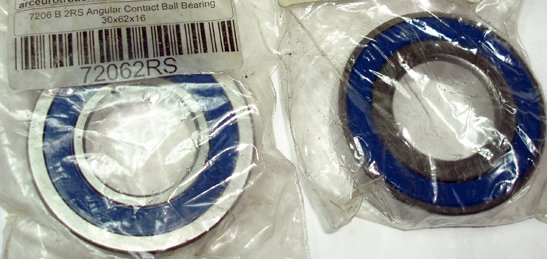
After installing the new bearings I decided to tram the column using a different approach and then to remove the head and square it.
To achieve best results in tramming the column, I used my 6 inch engineers square but as this was (is) my only reference to “square” I tried to eliminate any errors it possibly had by averaging the measurements taken to both ends of the table.
The method goes as follows:
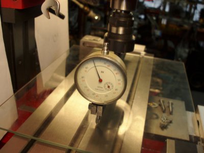
I used two 1-2-3 blocs bolted together and my engineers square side by side. Using shims (alu foil) I adjusted the inclination of the blocks in order to have the same DTI measurements on them (top & bottom) as to the engineers square next to them.
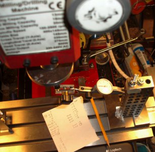
Next I secured the engineers square at the other end of the table and took measurements for the full height to left side and to the right side of the table moving the head and rotating the DTI.
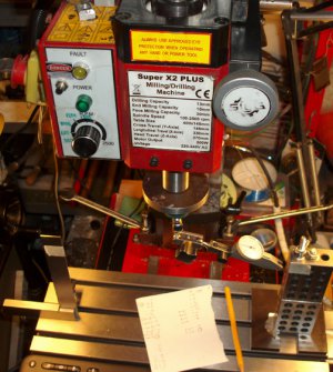
In the process, I recorded the results (bottom & top left, bottom & top right) and made adjustments until I got the same average for right and left side.
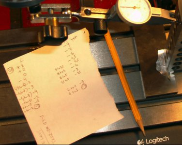
This way I was sure that the column was EXACTLY PERPENDICULAR to the table.
As I could not follow the same procedure for Y I took measurements putting the engineers square to the front of the table.
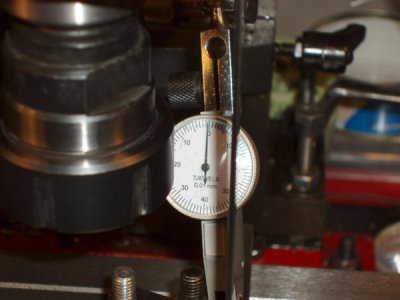
Next I started to work on squaring the head.
My mill’s head is bolted on a carriage with 4 bolts that are accessed from the back of the carriage after removing it from the column.
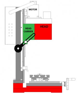
Because of this arrangement it is a time consuming work to make any adjustments to the head.
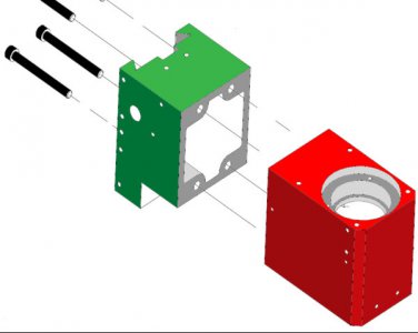
My head was far from square! In the “X” direction was 0.12 mm (0.005 in) out of square and in “Y” direction was out 0.05 mm (0.002 in) accordingly.
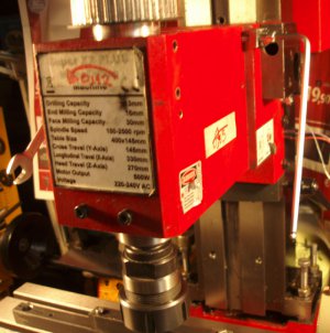
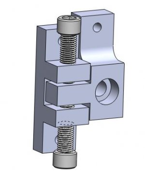
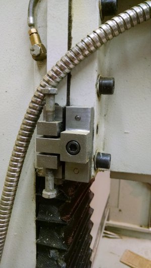
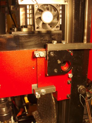
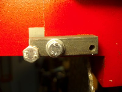
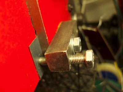
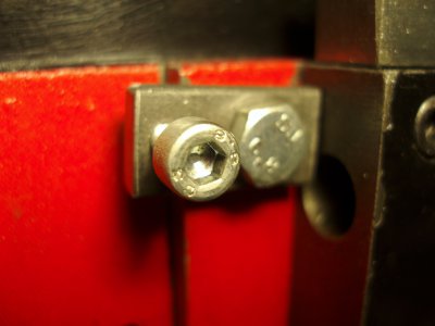
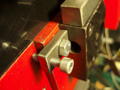
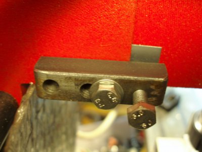
To make things easier I decided to add some adjusting bolts on the head carriage so I can make micro adjustments for the X directions. For the Y error I planned to use shims.
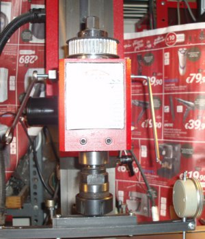
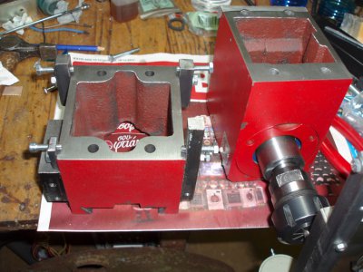
In order to add shims for Y and adjust the X, I removed the head carriage and the head, separated them and cleaned the mating surfaces on the surface plate.
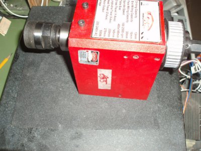
Then added the aluminum foil shims
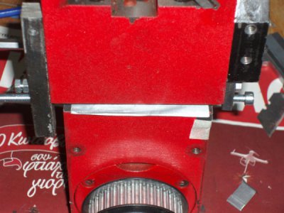
I hand tighten the 4 bolts that connect the head to the head carrier, I installed the head on the mill and using a DTI I tried to square the head.
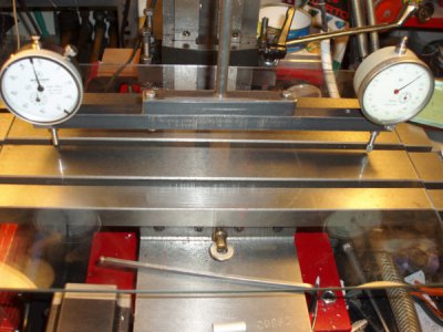
To my surprise, when I removed the head and tighten the screws further, the head was ok in Y direction, using the shims, but did not stay square in X direction despite the microadjusting screws that (supposed to) hold it in place!
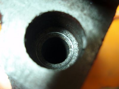
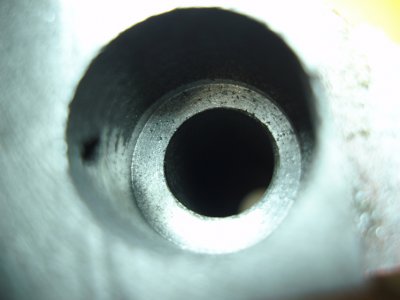
Several trials later I found the cause of this stubborn behavior! The 4 bolts connecting the head to the carrier had formed seatings to the concave bottom of the hole and as they were tighten they drove the head to the same position! No matter how hard I tried to change this position the head was always off in X direction by 0.12 mm.
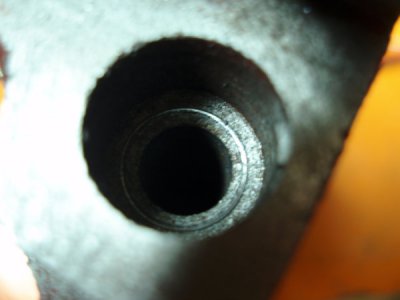
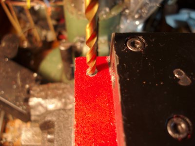
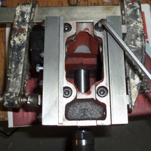
It was time to tackle the problem! As the mill could not mill itself, the only machine available was my mini lathe. Using shims I supported the head carrier on the topslide, secured it with c clamp, and using a 14mm end mill I made the bottom of each hole flat.
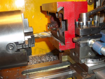
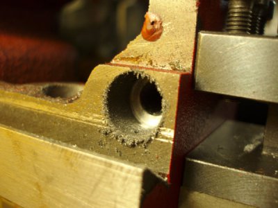
To play safe and have full control in micro adjustment I added another two micro adjusting screws to the carrier.
So now I could micro-adjust the top and the bottom of the head to achieve a perfectly square head!
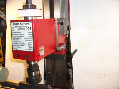
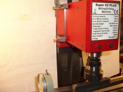
Tightening the bolts that secure the head to the carrier did not changed the head’s position.
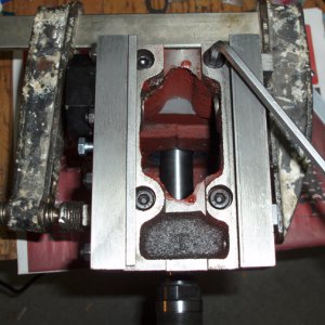
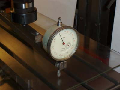
Measurements with my DTI certified an accuracy better than 0.01 mm (0.0004 in) at any height of the head!
I’m happy with that as I think there is no way to achieve better accuracy due to several other factors (flexibility of the column, flexibility of the base etc.)
Thanks for reading this
Petros
Although I was able to tram my mill within 0.01 mm (0.0004 in) these results were not permanent and I was always retramming my X2 mill blaming the long bolts, the Chinese designer, my TDI instruments, and my bad luck to buy a cheap mill.
This Christmas holidays I found some time to upgrade the bearings for some angular contact ball bearings that give better results compared to the stock plain ball bearings.

After installing the new bearings I decided to tram the column using a different approach and then to remove the head and square it.
To achieve best results in tramming the column, I used my 6 inch engineers square but as this was (is) my only reference to “square” I tried to eliminate any errors it possibly had by averaging the measurements taken to both ends of the table.
The method goes as follows:
I used two 1-2-3 blocs bolted together and my engineers square side by side. Using shims (alu foil) I adjusted the inclination of the blocks in order to have the same DTI measurements on them (top & bottom) as to the engineers square next to them.

Next I secured the engineers square at the other end of the table and took measurements for the full height to left side and to the right side of the table moving the head and rotating the DTI.

In the process, I recorded the results (bottom & top left, bottom & top right) and made adjustments until I got the same average for right and left side.

This way I was sure that the column was EXACTLY PERPENDICULAR to the table.
As I could not follow the same procedure for Y I took measurements putting the engineers square to the front of the table.

Next I started to work on squaring the head.
My mill’s head is bolted on a carriage with 4 bolts that are accessed from the back of the carriage after removing it from the column.

Because of this arrangement it is a time consuming work to make any adjustments to the head.

My head was far from square! In the “X” direction was 0.12 mm (0.005 in) out of square and in “Y” direction was out 0.05 mm (0.002 in) accordingly.

To make things easier I decided to add some adjusting bolts on the head carriage so I can make micro adjustments for the X directions. For the Y error I planned to use shims.

In order to add shims for Y and adjust the X, I removed the head carriage and the head, separated them and cleaned the mating surfaces on the surface plate.

Then added the aluminum foil shims

I hand tighten the 4 bolts that connect the head to the head carrier, I installed the head on the mill and using a DTI I tried to square the head.

To my surprise, when I removed the head and tighten the screws further, the head was ok in Y direction, using the shims, but did not stay square in X direction despite the microadjusting screws that (supposed to) hold it in place!
Several trials later I found the cause of this stubborn behavior! The 4 bolts connecting the head to the carrier had formed seatings to the concave bottom of the hole and as they were tighten they drove the head to the same position! No matter how hard I tried to change this position the head was always off in X direction by 0.12 mm.

It was time to tackle the problem! As the mill could not mill itself, the only machine available was my mini lathe. Using shims I supported the head carrier on the topslide, secured it with c clamp, and using a 14mm end mill I made the bottom of each hole flat.


To play safe and have full control in micro adjustment I added another two micro adjusting screws to the carrier.
So now I could micro-adjust the top and the bottom of the head to achieve a perfectly square head!


Tightening the bolts that secure the head to the carrier did not changed the head’s position.

Measurements with my DTI certified an accuracy better than 0.01 mm (0.0004 in) at any height of the head!
I’m happy with that as I think there is no way to achieve better accuracy due to several other factors (flexibility of the column, flexibility of the base etc.)


Thanks for reading this
Petros

