B
BRIAN
Forum Guest
Register Today
Taper Turning Attachment for 7 x 12:
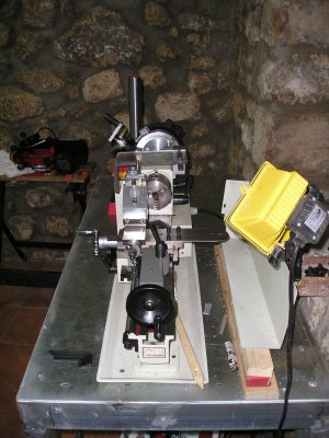
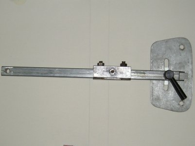
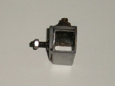
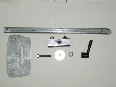
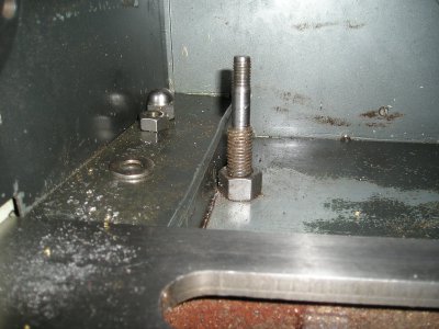
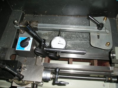
To fit the attachment to a 7x12 lathe we must first make room at the rear of the lathe and provide reinforcement to ensure repeatability. Split the splashback lengthwise and insert a piece of 2 mm steel sheet 20 mm deep, spot weld the three together and make a new end plate to fix with two screws. The studs shown in the photogragh go completely through the bench and provde support for the attachment. The pivot stud is 14 mm and reduced to 10 mm at the top to give a location for the sine bar, the others are 8 mm. The bar and traveller are made from square tube the bar is 20 mm x 390 mm the hole centres are 330 mm, the traveller is 14 mm square and 80 mm long. The traveller is reinforce on two sides for the cross side stud and brass adjustment pads. The cross slide plate and adjustment plate have been scanned full size on A4 SET UP first remove the cross slide feed screw. Fix the cross slide plate with 4 screws, set the height so the traveller moves freely. I use a DTI mounted on the cross slide to determine the setting of the sine bar I have a calibrated hand wheel on the lead screw (another mod) to accurately move the saddle 1 inch and measure the taper on the DTI. Happy Tapering ..... Brian. Photos on next post
To fit the attachment to a 7x12 lathe we must first make room at the rear of the lathe and provide reinforcement to ensure repeatability. Split the splashback lengthwise and insert a piece of 2 mm steel sheet 20 mm deep, spot weld the three together and make a new end plate to fix with two screws. The studs shown in the photogragh go completely through the bench and provde support for the attachment. The pivot stud is 14 mm and reduced to 10 mm at the top to give a location for the sine bar, the others are 8 mm. The bar and traveller are made from square tube the bar is 20 mm x 390 mm the hole centres are 330 mm, the traveller is 14 mm square and 80 mm long. The traveller is reinforce on two sides for the cross side stud and brass adjustment pads. The cross slide plate and adjustment plate have been scanned full size on A4 SET UP first remove the cross slide feed screw. Fix the cross slide plate with 4 screws, set the height so the traveller moves freely. I use a DTI mounted on the cross slide to determine the setting of the sine bar I have a calibrated hand wheel on the lead screw (another mod) to accurately move the saddle 1 inch and measure the taper on the DTI. Happy Tapering ..... Brian. Photos on next post

