- Joined
- Aug 22, 2012
- Messages
- 4,254
One step forward and two back.
As your knowledge base increases so does your recognition of past inadequacies.
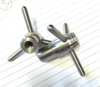
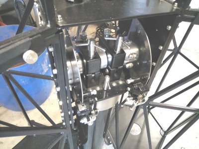
I bolted the two new parts on and found one was higher than the other by around 0.5mm
This led to more checks and I found the two lazy susan bearings were at slightly different heights and cants.
This was due to tiny discrepancies in the welded trusses.
I clamped the bearings to two long straight sections and aligned them as close as I could measure to 90 degrees to the optical axis.
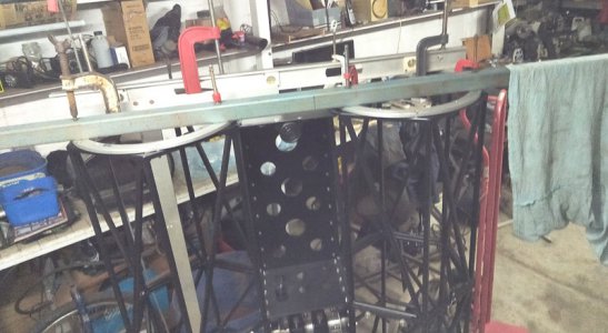
The T shirt hanging on the end is so I dont forget it sticks out and smack my head on it.
Dont ask me how I know that might happen.
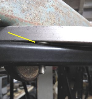
I then used different numbers of shims to keep that alignment as I bolted them back up.
The gaps ranged over 1.5mm with some only needing 1 shim and two that needed 4 shims.
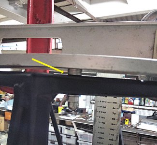
I will now do the same with the top cages when I bolt them on.
Then I can check the the two plates the new parts are bolted to are parallel and if they are not I can use the same method of shimming for them.
This has also led to the realisation that the over lock clamps that hold the tube together are not tight enough so I will re visit the captive bolts again to ensure a tight firm clamp. Good job I didn't dump them.
Ahh, I feel better just talking about it. I will feel even better when I get it done.
As your knowledge base increases so does your recognition of past inadequacies.
I bolted the two new parts on and found one was higher than the other by around 0.5mm
This led to more checks and I found the two lazy susan bearings were at slightly different heights and cants.
This was due to tiny discrepancies in the welded trusses.
I clamped the bearings to two long straight sections and aligned them as close as I could measure to 90 degrees to the optical axis.

The T shirt hanging on the end is so I dont forget it sticks out and smack my head on it.
Dont ask me how I know that might happen.
I then used different numbers of shims to keep that alignment as I bolted them back up.
The gaps ranged over 1.5mm with some only needing 1 shim and two that needed 4 shims.


I will now do the same with the top cages when I bolt them on.
Then I can check the the two plates the new parts are bolted to are parallel and if they are not I can use the same method of shimming for them.
This has also led to the realisation that the over lock clamps that hold the tube together are not tight enough so I will re visit the captive bolts again to ensure a tight firm clamp. Good job I didn't dump them.
Ahh, I feel better just talking about it. I will feel even better when I get it done.

