

- Joined
- Oct 28, 2020
- Messages
- 25
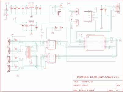
I've been using the DIY DRO Adapter Kit for Glass Scales for a few years and it works great. Now I'm looking to add tachometer support to the system and am running into some trouble getting the input to read reliably.
This is on a PM728-VT mill which came from PM with an Ancer RPM320M tach mounted with sensors. I'd like to retain the existing tach display on the machine. The existing tach runs at 5v logic levels so I can't directly feed that signal into the TouchDRO. Instead, I've wired up a level shifter so I can output the signal at 3.3v levels.
Checking scope traces, the resulting signal performs like I'd expect. I've added a 0.1uF cap across the power rails to smooth out some noise but it didn't make an impact. Blue trace (mostly covered) is +3.3 from the DRO PCB. Yellow trace is the signal coming back. Voltage p2p is 3.2V like I'd expect, the signal is reasonably clean without a lot of ringing on transitions, and the timing seems correct.

Zooming into a single pulse, there doesn't appear to be any ringing or overshoot, transition time is around 100us-ish.

When I set the speed such that the pulses are showing a frequency of 60Hz, the mounted tach shows 900 RPM which suggests 4 pulses per revolution. 30Hz shows 450, 90Hz shows 1350, so everything on the machine tach is ruler flat and works like I'd expect. When I set the speed controller, the RPM display doesn't bounce around and just shows the value.
In Touch DRO I've set the tach at 4 pulses per revolution and the device is showing an RPM but the value bounces around ±10% and the values are way off. Here's an example (sorry for the mess, guts are spilling out while I figure out what's happening here):

Here we see the machine tach (correct) at 905 RPM, while TouchDRO is 1815. Hey no problem, just set it to 8 pulses! Sadly, that relationship isn't quite as simple as 2x. Here are some example values:
Any suggestions as to what might be going wrong here?
This is on a PM728-VT mill which came from PM with an Ancer RPM320M tach mounted with sensors. I'd like to retain the existing tach display on the machine. The existing tach runs at 5v logic levels so I can't directly feed that signal into the TouchDRO. Instead, I've wired up a level shifter so I can output the signal at 3.3v levels.
Checking scope traces, the resulting signal performs like I'd expect. I've added a 0.1uF cap across the power rails to smooth out some noise but it didn't make an impact. Blue trace (mostly covered) is +3.3 from the DRO PCB. Yellow trace is the signal coming back. Voltage p2p is 3.2V like I'd expect, the signal is reasonably clean without a lot of ringing on transitions, and the timing seems correct.
Zooming into a single pulse, there doesn't appear to be any ringing or overshoot, transition time is around 100us-ish.
When I set the speed such that the pulses are showing a frequency of 60Hz, the mounted tach shows 900 RPM which suggests 4 pulses per revolution. 30Hz shows 450, 90Hz shows 1350, so everything on the machine tach is ruler flat and works like I'd expect. When I set the speed controller, the RPM display doesn't bounce around and just shows the value.
In Touch DRO I've set the tach at 4 pulses per revolution and the device is showing an RPM but the value bounces around ±10% and the values are way off. Here's an example (sorry for the mess, guts are spilling out while I figure out what's happening here):
Here we see the machine tach (correct) at 905 RPM, while TouchDRO is 1815. Hey no problem, just set it to 8 pulses! Sadly, that relationship isn't quite as simple as 2x. Here are some example values:
| Pulse frequency (Hz) | Machine Tach (RPM) | TouchDRO (RPM, set to 4 pulses) |
| 29.8 | 445 | 1110-1380 |
| 60.2 | 910 | 1695-1950 |
| 90.2 | 1355 | 2220-2505 |
| 119.9 | 1801 | 2580-3075 |
Any suggestions as to what might be going wrong here?
Last edited:
") I will clarify the pinout stuff (it sounded obvious to me when I wrote "input pinout", but I can read my own mind pretty good...). When I get a bit of time, I'm planning to order a bunch of HALL effect sensors and test how they work. For now, I'll at least add a short section on what "should" work.
I will clarify the pinout stuff (it sounded obvious to me when I wrote "input pinout", but I can read my own mind pretty good...). When I get a bit of time, I'm planning to order a bunch of HALL effect sensors and test how they work. For now, I'll at least add a short section on what "should" work.