- Joined
- Mar 26, 2018
- Messages
- 2,725
Ran into a bit of an issue yesterday and thought I might share my troubleshooting because I found it interesting.
My G0704 spindle is a custom design running an Alley Bradley MPL-A330P-MJ22AA AC Servo motor (1.8kW, 5000 rpm) and a 2098-DSD-020 servo drive (2kW).
This has been running for a few years really without issue, but yesterday when running a program the CNC would fault out when stopping the spindle for a tool change. This happened repeatedly and I had to stop what I was working on. The drive fault status goes to an input on the CNC so the program ESTOPs when there is a fault and displays an error message. When I opened the cabinet, the spindle drive would always be faulted on E10 - DC Bus Overvoltage.
The drives are powered at 240VAC and carry a nominal bus voltage of 325VDC. The DC bus overvoltage limit is 400VDC.
I just learned that the Ultra 3000 drives under the 3kW flavor do not have any DC bus shunting capacity so it can only absorb a small amount of energy which charges up the DC bus. The bus can only discharge by applying power to the motor or through natural resistive discharge (~80V/s).
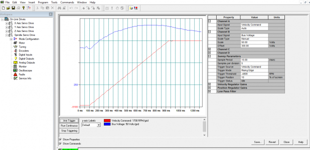
Here is a graph of spindle speed (forwards is negative velocity the way mine is configured). The spindle decels from -5000 rpm to 0 rpm over ~800ms. During this time the DC bus (blue) charges up from ~330VDC to ~380VDC and then dissipates back to 330VDC.
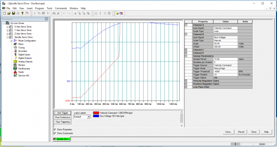
Compare this with a similar trend, except this time the bus charges up past 400VDC and the drive trips on E10 - DC Bus Overvoltage and the commanded velocity (red) is programatically set to 0 rpm.

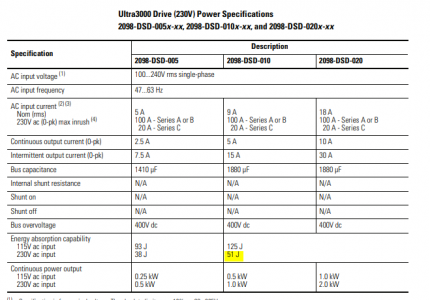
The Ultra 3000 specification manual states the drive (when powered at 230VAC) can absorb 51 Joules (J) of kinetic energy before the bus trips out on overvoltage. Since I power mine at 240VAC I can extrapolate the absorption capacity to be ~44.5J.

Using Solidworks, a quick approximation of the spindle + pulleys + servo motor rotational inertia to be ~0.008 lb*ft^2 (motor = 0.002847 lb*ft^2). When spinning at 5000rpm, this equates to a rotational kinetic energy of 46.21J. This is more than the 44.5J the drive can dissipate. The larger the tool installed, the higher this kinetic energy, although not by much.
I think I have gotten away without issue in the past because the spindle is approximately 90% efficient (10% of energy is dissipated in the belts and bearings as waste heat), so only 90% of the tool energy needs to be regenerated by the drive. I do not know why it has started causing issues now, perhaps something has loosened up and the spindle efficiency has increased.
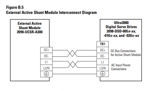
Anyways, my short term solution is to increase the accel and decel time from 800ms to 3.2 seconds which should give the DC bus more time to naturally dissipate. If that doesn't work, I have a 2090-UCSR-A300 Active Shunt Module which can be added alongside the drive to offer 300W of continuous shunting capacity (4kW peak). This is more than enough to handle any spindle shunting needs.
Just thought this was an interesting exercise.
Mike
My G0704 spindle is a custom design running an Alley Bradley MPL-A330P-MJ22AA AC Servo motor (1.8kW, 5000 rpm) and a 2098-DSD-020 servo drive (2kW).
This has been running for a few years really without issue, but yesterday when running a program the CNC would fault out when stopping the spindle for a tool change. This happened repeatedly and I had to stop what I was working on. The drive fault status goes to an input on the CNC so the program ESTOPs when there is a fault and displays an error message. When I opened the cabinet, the spindle drive would always be faulted on E10 - DC Bus Overvoltage.
The drives are powered at 240VAC and carry a nominal bus voltage of 325VDC. The DC bus overvoltage limit is 400VDC.
I just learned that the Ultra 3000 drives under the 3kW flavor do not have any DC bus shunting capacity so it can only absorb a small amount of energy which charges up the DC bus. The bus can only discharge by applying power to the motor or through natural resistive discharge (~80V/s).
Here is a graph of spindle speed (forwards is negative velocity the way mine is configured). The spindle decels from -5000 rpm to 0 rpm over ~800ms. During this time the DC bus (blue) charges up from ~330VDC to ~380VDC and then dissipates back to 330VDC.

Compare this with a similar trend, except this time the bus charges up past 400VDC and the drive trips on E10 - DC Bus Overvoltage and the commanded velocity (red) is programatically set to 0 rpm.

The Ultra 3000 specification manual states the drive (when powered at 230VAC) can absorb 51 Joules (J) of kinetic energy before the bus trips out on overvoltage. Since I power mine at 240VAC I can extrapolate the absorption capacity to be ~44.5J.

Using Solidworks, a quick approximation of the spindle + pulleys + servo motor rotational inertia to be ~0.008 lb*ft^2 (motor = 0.002847 lb*ft^2). When spinning at 5000rpm, this equates to a rotational kinetic energy of 46.21J. This is more than the 44.5J the drive can dissipate. The larger the tool installed, the higher this kinetic energy, although not by much.
I think I have gotten away without issue in the past because the spindle is approximately 90% efficient (10% of energy is dissipated in the belts and bearings as waste heat), so only 90% of the tool energy needs to be regenerated by the drive. I do not know why it has started causing issues now, perhaps something has loosened up and the spindle efficiency has increased.
Anyways, my short term solution is to increase the accel and decel time from 800ms to 3.2 seconds which should give the DC bus more time to naturally dissipate. If that doesn't work, I have a 2090-UCSR-A300 Active Shunt Module which can be added alongside the drive to offer 300W of continuous shunting capacity (4kW peak). This is more than enough to handle any spindle shunting needs.
Just thought this was an interesting exercise.
Mike
Last edited:

