Upgrading a Phase II XY table into a precision piece of equipment

Mark_f

Registered
Registered
Joined
Jan 16, 2020
Messages
5
I used a Phase II XY table when I built my Tool & Cutter grinder. While it is a decent positioning table, It is (like most of these) far from a precision piece of equipment. The mounting for the screw assembly and handles is poor quality and there is too much back lash to suit me. I plan to upgrade my South Bend lathe dials to large dials and realized the same setup can be adapted to the Phase II table and make it greatly improved. The new assemblies with roller bearings and hand wheels instead of those cheap little handles will make it smooth operating and very little back lash, thus making the quality of my machine greatly improved.

I have re-drawn the prints for the South Bend setup to work on the Phase II table.

The first part to make is the body that holds the roller bearings and screw shaft.
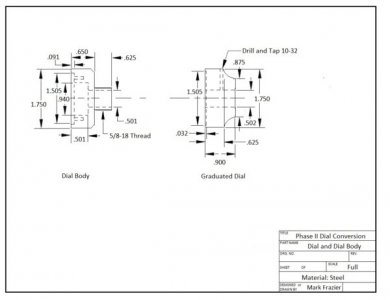
This is the updated print for the body and dial
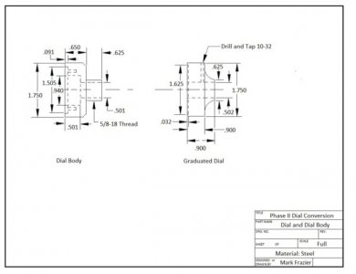
Dial and Dial Body.jpg


This table is practice for doing my South Bend lathe.

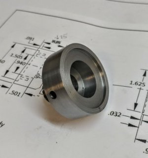
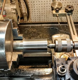
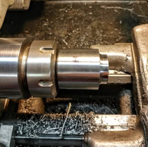
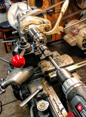
The body was roughed machined from 2" diameter Cold Finished steel. After the body was machined to the finished O.D., the center bore is drilled and reamed to .5000", and the counter bores are done in one setup to make sure everything is concentric. The piece is sawed to length and the rear side is machined leaving .020" for finishing. The piece is then super glued onto a piece of .500 drill rod and mounted in a collet on the lathe as in the photo below and finished to size, then threaded 5/8-18. This was done to ensure the concentricity of the bore to the mounting threads.
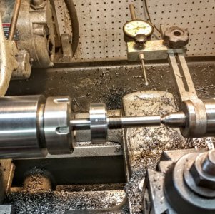
threading and turning setup.jpg
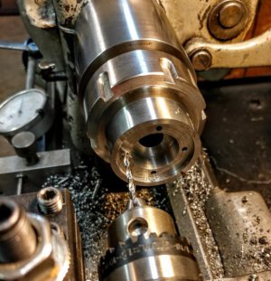
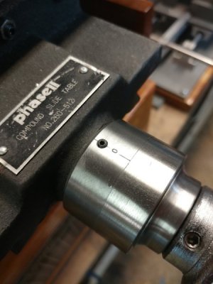
While in this setup, the zero mark is engraved and a pin hole is drilled for a pin wrench to install the body in the table.( in the photo, I engraved the zero mark to the wrong side of the body. This is an easy fix and will be corrected).

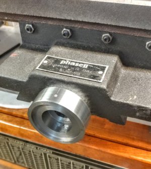
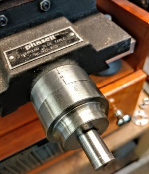
The hole in the front of the Phase II table where the screw mounted just happened to be the right size for a 5/8-18 tap, so after tapping the table and the body is all machined and threaded it is check for fit in the table
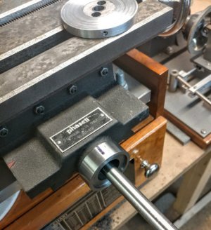
chcking fit to table.jpg
. The rod is still super glued into the body and the body is tightened into place, the place for the zero mark is located and also the place for the pin wrench hole.
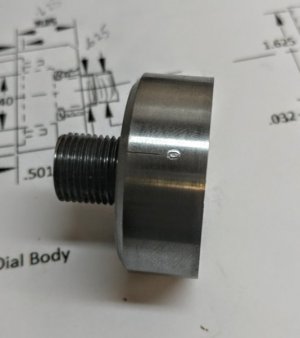
zero mark.jpg
pin hole in body.jpg
The next step is to finish the body by drilling the holes to mount the retaining plate that holds the bearings in place. It is a round plate 1.500" diameter and about .100" thick. The plate is made by chucking a piece of 1.50" CR steel in the lathe, facing the end and drilling .50" into the piece with a 1/2" drill. Then a thin slice is sawed of in the band saw. There are many ways to drill the plate and body. I put the body in a 5/8"collet in the lathe and used my cross drilling fixture to drill the plate and body together. The holes are tapped 4-40 .375 deep. the screws are flat head screws. The assembly is put in the lathe and the sawed surface is faced flat and even with the body.
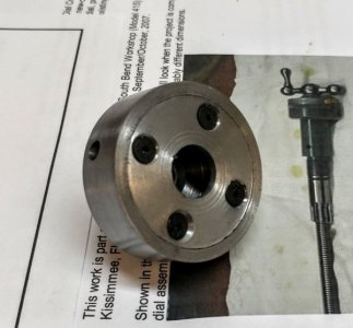
completed body.jpg
This is the completed body. You can see the hole for the pin wrench.
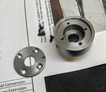
body parts.jpg
The body parts

body mounted in table.jpg
The body mounted in the table.


The next step will be to make the screw and fit it to the body and bearings.


More to come...............
 
Very nice work
Will you be changing the lead screws and nuts to something a little better?

Ray
 
I am making new screws. The nuts are cast iron but are very tight as this table was new. Someone had left it get rusty and I cleaned it all up. I will be making bronze nuts later and also making brass gibs.
 
Well, I got the first axis assembled and installed it and guess what..... it was tighter than a frog's butt. This takes a little thinking. I know I held my tolerances to less than .oo1". When I remove it from the table, it works fine.... ???????..... so I start figuring.... if I miss a dimension on the shaft by .0005", the body by >0005" , that is .001" error which gives the possibility of .002" total error depending on which way the error is located.
with the tolerances I tried to hold, this could bind it up. I also don't know how accurate the Chinese were when making the table ( I bet it wasn't as close as I was trying to hold) and this can cause more error. So, it was my conclusion that you must make this stuff as close as possible and the "fit" everything upon assembly.
20170617_163109_HDR_resized.jpg
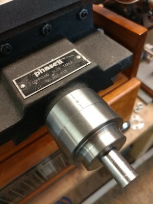
This is the assembly installed. it is TIGHT. So i took it apart leaving the body and screw in the table. If I unscrew the body it is free, but tightens when the body is screwed into the table. There was only .0005" clearance on the shaft in the body. while this is OK in a perfect world , my world evidently isn't perfect. I polished the shaft to get .0015" clearance and know the shaft fits into the body good. I put the assembly together without the roller bearings to check something. with metal on metal rubbing I canot move the table without putting a handle on the .500" shaft. it is just too stiff and this how it was before the upgrade. Next, I put the bearings in and now it moves very easy and smooth. I can turn the .500" shaft with my fingers and move the table. I REALLY GONNA LIKE THIS UPGRADE!!

20170617_164021_HDR_resized.jpg
This photo shows one of the bearings. There is another bearing goes on the front and the cover plate goes on with (4) 4-40 screws. The shaft was turned from 1" diameter CRS. the .935" diameter part will get machined to a thickness to give .001" to .002" of preload on the bearings. This ensures there is "zero" back lash in the screw assembly. The screw and nut has about .003" back lash. The nut is also a bronze nut. so I went from a hard to turn table axis with .025" of back lash to a smooth easy turning axis with .003" back lash. Now to start making the parts for the other axis.

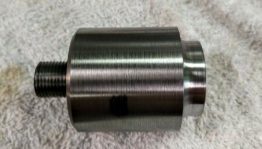
I figured out instead of making the body and dial separately, I would machine the OD , drill and ream the Piece all at once and turn the threaded part that screws into the table all in one setup and eliminate any error.
20170617_165446_HDR_resized.jpg
After this piece is reamed, the stub turned and threaded, It will get sawed into the body and the dial and should fit with less work. The only error is in the table construction and I just have to work around it. But this upgrade is so great, I can't believe the improvement. It is well worth doing.

You may have noticed there are no graduations on the dial yet. after both axis are done, I will remove the dials and set up my dividing head and mark both dials to make it easier.


Still more to come......

20170617_163118_HDR_resized.jpg
 
this is an updated print. There were some dimensional errors on the previous one.
Dial and Dial Body.jpg
 
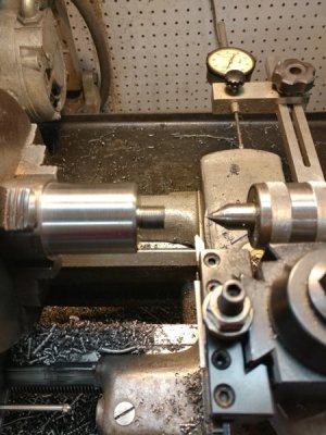
After turning the OD, I drilled and reamed the piece of bar stock 2 /12" deep at .500 diameter , I turned the stub and threaded it 5/8-18 to screw into the the table.
20170618_104546_HDR_resized.jpg

20170618_111409_HDR_resized.jpg
The piece was sawed off and turned around in an ER 40 collet to turn the profile on the dial.

20170618_111415_HDR_resized.jpg
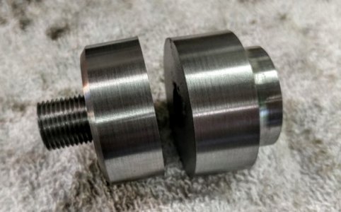
This is how the part looks when this phase is done.

20170618_114112_HDR_resized.jpg
The piece was then sawed in half to make the dial and the body. these pieces can now be finished on the ends using the ER 40 collets. By doing the machining in this order, I have both parts perfectly concentric on all surfaces and no detectable error. this should make fitting everything easier. These two pieces will be for the X axis.

Lead Screw Extension.jpg
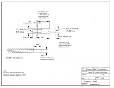
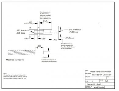
This is the preliminary print for the lead screw modification. The end of the lead screw has been turned to .375" diameter and cut to .800" long. It is then lock-Tite into the shaft extension and a 3/32" pin installed through the two pieces. You may notice that there are some dimensions that are "fit". I will put oversize preliminary dimensions here but they will be fit at assembly.


Be patient ..... this project will be winding up soon. This is a n easy upgrade ( I know it looks complex) , you just have to watch the tolerances and be patient.
 
Ok ........ I'm going to wrap up this project and provide some details that may help anyone else that may want to do this upgrade.


The next two photos show the details of how I drilled the screw holes for the bearing retainer plate. I used my cross drilling fixture with my degree wheel to drill 4 holes every 90 degrees on a bolt circle. The second photo is a close up view of drilling the holes.
drilling the screw holes.jpg close up of drilling screw holes.jpg


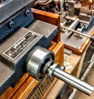
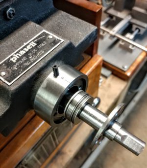
This photo shows the bearing details. There is a thrust roller bearing on the rear of the screw extension and one on the front. The flange on the screw extension has been machined to give .002" preload when assembled.
bearing assembly details.jpg


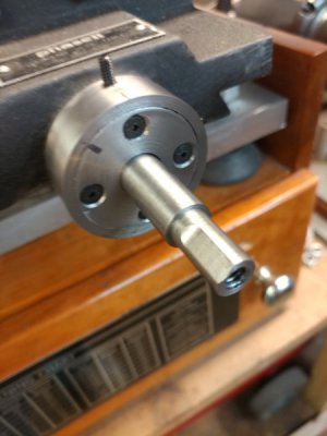
The bearing retainer plate is installed. The flange on the lead screw is captured between the bearings and there is zero back lash in this assembly. ( that set crew in the photo will be explained shortly). The shaft has been turned to fit the hand wheel and a flat milled for the set srew. the end is drilled for a 1/4-20 bolt that also holds the hand wheel on.
bearings installed.jpg


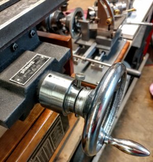
And here it is ........ The finished upgrade. The dial is installed to check the fit. The hand wheels were my first upgrade on this table and they are a lot better than those little crank handle that came on it. There is a 10-32 stainless steel thumb screw (I buy these at Home Depot) that locks the dial in position. There is a piece of brass rod .125" long inserted in the hole under the thumb screw to protect the shaft.
completed assembly.jpg


And now for that 6-32 set screw. It is a plug for the oil hole that allows oiling the roller bearings and shaft.
oil hole.jpg
This axis is finished and I couldn't be more pleased with the results. There is only .003" backlash and that is in the lead screw and bronze nut. This axis moves very easy and silky smooth in both directions. It came out so perfect ...it is scary! I am much happier with this grinder with this upgrade. I am about finished making all the pieces for the X axis. It will be done the same way.

You will notice there are no graduations on the dials yet. After the y axis is complete, I will mark and stamp the graduations on both dials at the same time so as to set up for it only once. I have posted several write ups in the past about marking graduations and stamping numbers in the past, so I won't be covering it here.

Thanks for watching....

I have attached the up dated print for the lead screw modification
Lead Screw Extension.jpg
 
I have a PDF file of the complete upgrade but the site won't let me upload it, so if anyone wants it, send me your email and ask for it.


EDIT: This file is too large to email and too large to upload here. At the moment, I don't know how to get around this. All info in the file is also in this thread.
 
Last edited by a moderator:
Thanks for documenting this Mark, it looks great!
Early on you mentioned making brass gibs. Did you find this to be unnecessary after the bearing upgrade was complete, or is it still on your to-do list?

My email address is on the way. I'm not ready to tackle something like this yet, but it will eventually be within my skill set (I hope!).

I thought this table had cast iron nuts but found they were in fact bronze. I also purchased some acme threaded rod from McMaster Car to make new screws but found I didn't need it because this table was practically new when I got it ( someone had left it outside or something and it was rusty) and there is no wear on the screws and nuts. They have .002" .003" of back lash, so I just modified the original screws. I thought I would need to change the cast iron gibs to brass to get the smooth operation I was looking for , but after this upgrade it won't be necessary. The bearings have made this a very smooth operating table. In fact it is better than my lathe and mill. I will be doing this upgrade to my lathe and mill as well. The 1 3/4" diameter dials will be much easier to read than the little 1" dials that were on here.

This upgrade is really very easy to do. the hardest part (for most people) is watching the close tolerances (I am used to working to .0005" tolerance). I can't say enough about the difference. It turns this table from a cheap import piece of junk to being equal to the quality tables costing ten times as much. I think any hobbyist can do this. You don't have to be a master machinist. Just take it slow and be patient.
 
Back
Top