WF & John Barnes Drill Press

Rick_B

Active User
H-M Platinum Supporter
Joined
Dec 10, 2011
Messages
447
The machine is a small bench top drill press manufactured by WF & John Barnes. The machine appears in the 1898 Metal Working Machinery catalog on Vintage Machinery (no other metal tools catalogs are available so I'm not sure how long this machine was offered. I have not found any other mention of it anywhere. Here's a link to the catalog - the machine appears on page 2. http://www.vintagemachinery.org/pubs/73/15144.pdf

It is called a Bench Friction Disk Drill. It has a wheel on the spindle that rides against a disk, which is powered through a flat belt pulley system. Moving the spindle wheel's position on the disc increases/decreases the spindle speed from 0 to 1650 rpm. Column to spindle is 4-1/4" so it would be considered an 8-1/2" drill by normal standards. It 33" tall, has a spindle movement of about 3" and weighs 65#. It came to me powered by a 1/4 HP, 1725 RPM single phase (I think) Western Electric motor. I thought I'd at least get the disassembly started today. After about 1-1/2 hours I was done.

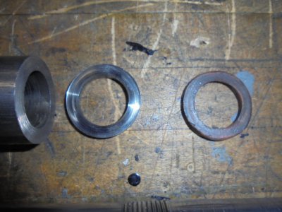
I'm having some trouble understanding the spindle assembly and was wondering if anyone has ever worked on this or a similar machine that could suggest just how the spindle and quill went together. Here's a few pictures of the machine as received

As Received 1.JPGAs Received 2.JPGAs Received 3.JPG
 
Here's a picture of the spindle and parts after cleaning up
View attachment 398167Spindle Parts Clkeaned Up.JPG
No real bearings' Going from left to right
threaded cap that threads onto the spindle and holds everything on
Steel piece/washer
Brassy looking piece that has a raised ridge on the outside diameter and a curl cut/worn off. There is also a pin in this piece that appears to fit in the spindle keyway. The keyway stops at the quill so that piece would need to go on top.
Quill - has a slot in the top = no idea why
Another steel piece that has raised ridges on the OD
What appears to be a fiber type washer

It has been suggested to me that perhaps there were thrust bearings on the spindle that wore out and some attempted a fix? Not sure - I am hoping someone has taken a Barnes spindle apart and can enlighten me. Soem pictures of the parts above
Brass Worn Piece.JPGDSC01371.JPGPin in Brass Piece.JPGSlot in Top Of Quill.JPGTop Pieces.JPG
View attachment 398162View attachment 398163View attachment 398164View attachment 398165View attachment 398166
 

Attachments

  • Bottom Pieces.JPG
    Bottom Pieces.JPG
    134.6 KB · Views: 2
That‘s a beauty.
Martin
 
The slot in the top was for oiling the quill, old machines commonly had steel against cast iron as a bearing surface, fiber was commonly used as a thrust surface. I have a Xerox copy of a catalog dated August 15 1897 that shows the benchtop drill fairly similar in its details to what you show, but with differences, in your machine the spindle is started and stopped by the tight and loose pulleys, in my catalog, there is only one pulley is on the shaft and the power is engaged by bearing the disc against the spindle roller, the speed is locked in place by a rod and clamp screw behind to spindle, not to the left side as your pics show with the lever to position the roller on my cat illustration, there is a finger loop in front of the spindle. Yours is an obviously improved model.
 
The slot in the top was for oiling the quill, old machines commonly had steel against cast iron as a bearing surface, fiber was commonly used as a thrust surface. I have a Xerox copy of a catalog dated August 15 1897 that shows the benchtop drill fairly similar in its details to what you show, but with differences, in your machine the spindle is started and stopped by the tight and loose pulleys, in my catalog, there is only one pulley is on the shaft and the power is engaged by bearing the disc against the spindle roller, the speed is locked in place by a rod and clamp screw behind to spindle, not to the left side as your pics show with the lever to position the roller on my cat illustration, there is a finger loop in front of the spindle. Yours is an obviously improved model.
I wouldn't mind having a copy of that catalog page if you wanted to share

Rick
 
I wouldn't mind having a copy of that catalog page if you wanted to share

Rick
Our computer does not have a functional scanner, but I could copy it and send by USPS, PM me with your contact info.
John
 
Looks like it was machined with races for ball bearings, much like older motorcycle head-stocks. Mike
 
While thinking about the spindle assembly I have been cleaning up other parts

Base
DSC01367.JPG


Base Cleaned Up 2.JPG
Base Cleaned Up 1.JPG

Dealer Tag
Dealer Name Plate (1).JPG


Other Parts
Other Parts Cleaned Up.JPG

Back to the spindle - I received some comments both here and from other forums relating to the spindle construction' Based on this I have developed a working theory that can be used as a jumping off point for discussion.

Bottom of Spindle

Theory - Bottom Of S;pindle.jpg

There is a flat steel disc that rests against the bottom shoulder of the spindle. Nest to that is the phenolic/fiber/bakelite disc that serves as a thrust washer. The quill then sits on top of that washer.

Top of Spindle

Theory - Top Of Spindle.jpg

The general feeling is that machines of this age would have used loose ball bearings between an upper and lower race. The steel disc with what appears to be a machined race sits on top of the quill. The side opposite the race has a raised edge but does npot appear to have a race machined into it. Then would be the loose ball bearings (Which I don't have yet followed by the brass upper race. Remember the brass race has a pin that fits into the spindle keyway. This locks the brass race to the spindle and it revolves with the spindle. Locking everything together is a threaded cap. The slot on the quill is on top for lubrication. Still not sure where the sliver of brass came from - maybe the pouter edge of the race?

I have an assortment of bearing balls arriving that I can try. There is nothing in the above theory that is cast in concrete except the brass race has to go on top of the quill - it won't fit over the spindle because of the pin. I'm not sure how thrust bearings and thrust washers work so the arrangement
of the pieces and parts is all up for discussion - as well as the big picture theory.

Rick
 
Back
Top