What job did you do today in your shop?

finished welding together a steel flatcar. There will be outriggers on it. The flatcar will host a steel derrick for lifting stuff off barges to railcars or the other way around.

Wow! How absolutely cool! I love reading old issues of Modeltec, and seeing the incredible trains and tracks people actually build in their yards!! Is this your yard??

Bernie
 
making a new hyd work station, rams for forming , rams for pressing, rolls for forming plate/stretching plate, this is the hyd motor mtg plate, it has 7 mtg holes so rhino CAD is invaluable
i have a hyd power pack which used to control the steering for ships water-jets the valve coils are 24 vdc
here is the old workstation, I just want to make a good pro one
 

Attachments

  • Screenshot (615).png
    Screenshot (615).png
    592.4 KB · Views: 47
  • 20201118_175239.jpg
    20201118_175239.jpg
    1 MB · Views: 35
  • Screenshot (612).png
    Screenshot (612).png
    169.8 KB · Views: 28
  • 20181013_114307.jpg
    20181013_114307.jpg
    1.3 MB · Views: 30
Well I got back home yesterday from threeweeks of work in East moline, IL. So I got on cleening up the mill I got the day before I left. I pulled the table off the X Y and pulled them apart. I have them all cleaned and waiting on me to clean the base and head. the mill dose not look abused just neglected. I mean it looks as though it was never cleaned. He had a fixture plate on the table, so he never used the t slots other than to hold the plate on. this also means he never cleaned them.
View attachment 161601View attachment 161603View attachment 161605View attachment 161607View attachment 161609View attachment 161612View attachment 161614
If you lookat the screw close you can see a line of small burrs it looks like it got dragged, i will hit that with a little emery.
keep your hands out of the spinning things​

View attachment 161602

View attachment 161604

View attachment 161606

View attachment 161608

View attachment 161610

View attachment 161611

View attachment 161613
lotsa work, some i wish i had , a mill
 
I reworked a cheap and poorly made angle vise that came among the tooling with a previous Smithy Granite. I made the decision to machine the moving jaw ways once I determined that the bottom was reasonably flat. My inspection influenced that decision because it showed that one side of the ways was parallel to the bottom well within 0.001" (an accident probably) but the other side was not parallel to the bottom and the lowest point was 0.009" below the "good" side. I hesitated taking anything off the ways because the movable jaw relies on those surfaces to keep itself from spinning around on the one shaft that controls it's linear movement. Sure enough, when I got both ways flat and parallel to the bottom, the movable jaw had 0.005" clearance between it's feet and the ways. What to do? I went to the hardware store and bought some nylon bolts and drilled/tapped for one on each side. This allows me to adjust out the slack I created under the movable jaw. After confirming that I had the vise installed against a repeatable stop, I milled the fixed jaw to be perpendicular to the base and parallel to the carriage travel. Clamping a parallel between the jaws then allowed me to machine the face of the movable jaw parallel to the fixed jaw. I dressed up the rough casting on the top of the jaws and milled flats on the tilt dovetail ends so I could easily zero out or confirm zero tilt by feel. There is an adjustable stop for that. Then I could replace the improper screws that held the jaw faces in place. The last step not done is to trim the fixed jaw screws flush with its face. I debated whether to turn the screws around for a more appropriate orientation (bolt heads countersunk in the removable jaw and threaded into the body of vise and moveable jaw, but the new bolts seemed to work OK. The fixed jaw face is resting on a freshly milled step, so the bolts are not the only thing holding it in place.

Now I'm ready to re-machine about half the pins that I need for the long threaded rod handscrews I'm making. This time I'll use the notch in the fixed jaw of the vise so they cannot slip. Somehow, they got drilled and tapped almost 10° from perpendicular. I was holding them in a 5C collet with a stop and didn't notice or remember that such collets only grasp the part at the end of the collet. The pressure of the drilling must have pushed them catywampus. The collet really didn't have a chance on such a short part. A machinist's jack would have cured the problematic setup had I noticed it happening. Zu früh alt, zu spät klug.

DanK
 

Attachments

  • IMG_20211012_191045676.jpg
    IMG_20211012_191045676.jpg
    1.3 MB · Views: 36
Made this accordion fold way cover for my Smithy 1324. Rubberized fabric glued to posterboard. Tedious but not real hard. Haven't decided how to secure the left end yet. Kinda hate to drill and tap holes...yet.
DanK
 

Attachments

  • IMG_20211222_103715778.jpg
    IMG_20211222_103715778.jpg
    132.8 KB · Views: 26
That looks great, a tutorial would be sweet!
OT here but the other night we were making rain on set. The telescoping camera crane had bellows to cover the 20' boom, the operator told me it was fragile and cost $20,000!
 
These accordions cost less than $10 for two starting with two poster boards 28" x 15", 3M 77 spray adhesive, and a lightly rubberized fabric. The time consuming part was laying out, creasing, and folding the posterboard. This video uses a paper to illustrate, but on a panel this big, the posterboard is unmanageable as he does it. I simply measured, creased with a dry ball point following a straight edge, and folded alternate scores opposite directions. Then I laid out the "drops" being sure the center span would cover what I needed. The start of the drops is drawing (not score) two lines at 90° to the long folds as far apart as the long fold scores, in my case 1/2". That forms a line of squares where the drops begin. Using a drafting square, i scored 45° lines zigzag fashion in the squares across the sheet. Then comes the tedious part of folding the drops. A small aluminum angle iron under the sheet helped a great deal, almost making the drops form automagically. Then I flattened the posterboard and sprayed the adhesive on both board and fabric and let it dry. Then using a series of dowels to keep them separated while lining things up, I pressed the center of one edge into contact and pulled the dowels out gradually pressing the layers together from center out. It requires more patience than skill. With the fabric attached, the folds need some encouragement the first time after laminating, but again using the angle iron (corner up again) helped a LOT.
DanK
 
Over the weekend, I sharpened more than 100 drill bits with the new Drill Doctor 700X. Sizes ranged from 3mm to 3/4". Now, I have to find a good way to sort them for easy identification.
 
Over the weekend, I sharpened more than 100 drill bits with the new Drill Doctor 700X. Sizes ranged from 3mm to 3/4". Now, I have to find a good way to sort them for easy identification.
maybe get a slab of wood, dress it up draw lines on it n drill along the line
or turn a piec wood round put concentric circles on it in the lathe , too easy
 
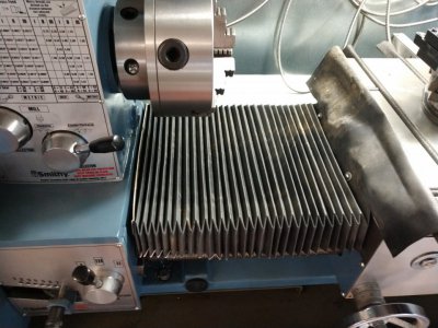
I made a gear. My first gear. It’s a modulus 1.5 62 tooth change gear for the Takisawa, with a 22mm hole with a 3/16” key, I tell you, if you read the page after page in Machinery’s Handbook, it looks formidable. But “metric” gears, identified with a mod number, are a cinch. Here’s how it goes: First, you need to know the outside diameter of the gear. Ok, it’s the number of teeth plus two, times the mod number, answer is in mm. So, (62+2)*1.5=96mm. Make a blank that diameter, thickness whatever your other gears are. Then, buy a set of mod 1.5 cutters, $80 on eBay. Mine were a 22mm arbor hole, so I had (got) to make an arbor. Easy, and making it all in one lathe setup means zero runout issues. Then get a $275 dividing head, also eBay. It’s a 40:1 crank ratio, so for 62 teeth, 40/62 is zero remainder 40/62, from third grade math or so. 40/62 is also 20/31, so use the 31 hole ring on the dividing plate, and move 20 holes for each teeth. I had an expanding mandrel that I stuck the gear blank on and chucked in the dividing head. Align the dividing head on the mill table so the mandrel indicates square with X axis and parallel to the table. Position the midpoint of the cutter vertically with the midpoint of the blank, touch off and advance the cutter to a depth of (2.25) *mod number = 2.25*1.5 = 3.375mm depth of cut. Now just make the cut, turn the dividing head crank 20 holes, and repeat 62 times.

Maybe that one gear doesn’t look like a bargain, but the next one is only half as much. :)
 
Back
Top