Milling Rite

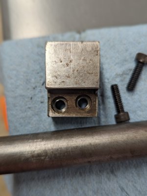
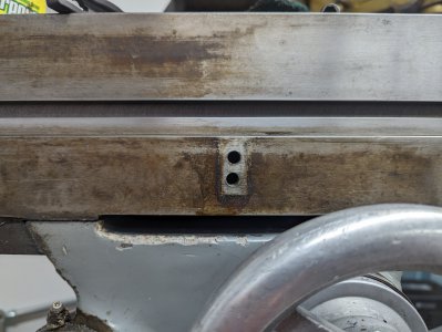
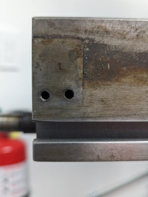
Question: why the hell are these two holes so slanted?

Pictured: ...and why aren't they chamfered?
1000025731.jpg


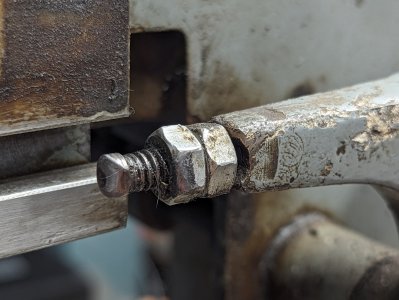
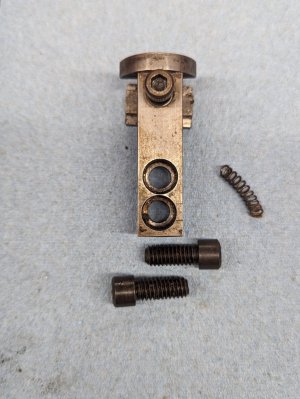
I honestly don't think the manufacturer would have drilled those that far out of vertical or left them unfinished...nor do I think they would have built this next widget to an equally-drunken alignment.

Pictured: Like, for seriously: dafuq?
1000025732.jpg


I vaguely recall pulling this off of the saddle, but I have no idea where that spring was located. It's VERY dead, regardless...so, into the Box of Shame it goes. And while we're at it...

Pictured: These holes are kind of uncool as well.
1000025733.jpg

1000025734.jpg


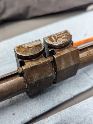
So, here's my theory: either this X-axis powerfeed is an aftermarket thing entirely - and that's what all of these parts are for, incidentally: it's the auto-stop system - or they were made badly and located on the table based on the existing manufacturing errors. And after that, the entire system was somewhat beaten and bashed.

Pictured: Ugh... this is gonna take some work.
1000025735.jpg

1000025736.jpg

1000025737.jpg
 
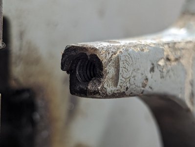
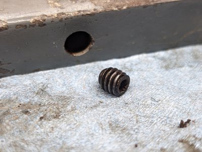
Turns out that the other side of the stop cam/lever/dingus has a through-hole that was tapped... and which had a set screw buried under a few decades of grime. I'm starting to think that I was bad in a previous life.

Pictured: But at least the screw came out.

1000025740.jpg


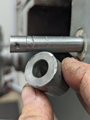
Also, the shaft upon which that piece rides turned out to be in... questionable...shape. I had to take a key file to it to knock down the deformations and allow the bushing/collar/widget to slide off, whereupon I discovered a lovely set of hammer marks that the previous owner left in what could only have been a bout of impatience and/or some type of simian rage.

Pictured: But at least it did come off.

1000025739.jpg


Is this the point where I just say "smurf it" and just tear the entire thing apart and restore it? If not, I feel like I'm quickly approaching it.
 
Is this the point where I just say "smurf it" and just tear the entire thing apart and restore it?
Probably a good idea. Likely to find many things that can be improved/fixed that are not obvious.
When you get finished, next year, lots of photos of the adventure.
 
Probably a good idea. Likely to find many things that can be improved/fixed that are not obvious.
When you get finished, next year, lots of photos of the adventure.

That's what I'm scared of: it'll be next year before I get this thing running...and I have stuff to make in the meantime.
 
As soon as my longer tool appears, everything will change: the right side bracket will just slide right off, the entire machine will clean itself, rainbows and unicorn tears will rain down from the heavens, cats and dogs will live together in harmony, etc, etc.
I love your sense of humor!


I contacted Kurt Workholding to see what they had to say on the subject...and succinctly, it was "We've never seen it done, so let us know what you figure out." They're sending me some diagrams of their parts so that I can think on it, as well; right now, my thoughts are:
  1. Swap the step pulleys to a single-speed arrangement and install a VFD, and use a mount based around the motor area.
  2. Rearrange the pulley cover in order to create some real estate on the front side of the machine and start working from there
  3. Abandon all hope.
Option 3 is the easiest, of course.
You’re going to want at least a couple different pulley speeds with a VFD, so I would not recommend a single speed pulley setup. The motor that is on it was likely made before VFDs were common, so it might not play well with a VFD if you over speed it, or try to run at very low speeds. I have kept the original pulleys and limit my lower speed to 25% of full speed and change the belt setting as needed for the cutter diameter and material.

My table doesn’t have any of those crooked holes you show, so my guess is someone did that along the line.


Is this the point where I just say "smurf it" and just tear the entire thing apart and restore it? If not, I feel like I'm quickly approaching it.
Since you have some projects you need to do, I would take care of the major issues now and then plan out looking at each section at a future date. Once you use it for a bit, you will figure out what is important and what can wait. Larry is right, if you keep taking it apart, it can easily be next year before you get it done.
 
Well, the table is off...

Pictured: That was surprisingly easy.

1000025742.jpg


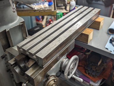
I just slid my rolling work table into position and then cranked the table down until it contacted the first block. It slid out easily and I didn't really even have to fight it at the second block; I just jockeyed the vertical position a bit, picked up on the distal end slightly, and it came right off. Then I slid it around a bit more to get it nice and stable, wheeled the table out of the way, and vomited.

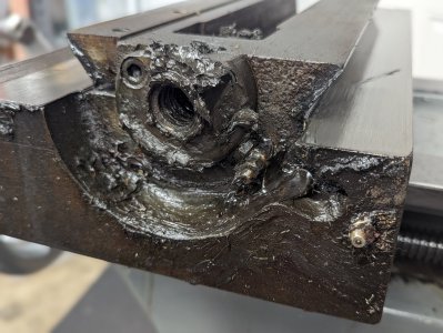
Pictured: The sludge is strong with this one.

1000025745.jpg


I don't even know how you get THAT much grease everywhere, but I think it was spilling out of the entire of the leadscrew nut. The surface of the saddle didn't look that bad, surprisingly.

Pictured: Not so terrible.

1000025743.jpg


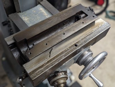
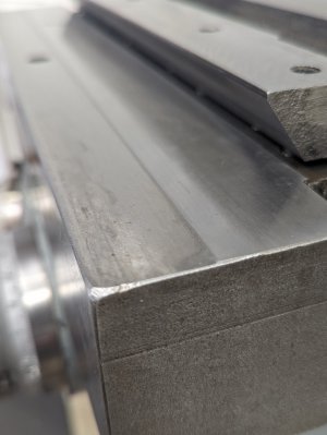
That's exactly as I found it, excepting one finger smudge. Greasy, yes, but not completely filled with disaster... but there's definitely some kind of wear pattern present on it, and I'm not sure how to interpret it.

Pictured: Shown here.

1000025749.jpg


That section on the left is a significant bit lower than the area on the right...but I'm not exactly sure what that means, if anything.

I'll get some pictures of the rest of what I found, here in a bit. If nothing else, at least I'm getting an education in how this thing is put together.
 
That is a royal smurfload of grease. There is only one explanation... the prior owner must have been a farmer.

I am pretty sure the step in the bottom way is intended. It's pretty clear in the chamfer on the end. The contact surface is only half the width. Too wide an area would make the slide hard to start, so it's rebated.

I'm willing to bet the power x feed was installed on the factory floor at the end of the assembly line after the mill was built. That would mean some junior factory worker had to line up the stops, hand drill the holes, tap them, and install the parts working from bowed knee, probably while the painter was working around him and another guy was installing data plates at the same time. While I'm on an assumption tear, it's probably a spec-to-order job that only a few of the mills received, like factory cruise control or curb feelers.

You've made it this far, no reason to make a half-smurfed job of it. Might as well go buy the big jug of simple purple and go to town. You'll be glad you did when it's done.
 
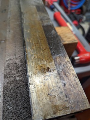
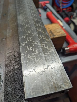
And here's the underside...

Pictured: Before...

1000025752.jpg


Pictured: ...and after-ish.

1000025753.jpg


It doesn't seem that bad...but I also don't know what I'm doing, so I'm just assuming that so many intact scrape marks are a good thing. I didn't really scrub it; I just kind of went over it lightly with some penetrating oil and a Scotch-Brite™ and then a blue paper towel...so, let's hope I didn't screw anything up.
 
That is a royal smurfload of grease. There is only one explanation... the prior owner must have been a farmer.

Toy-train maker, believe it or not...but there was a lot of Idaho farming going on nearby, for sure.

I am pretty sure the step in the bottom way is intended. It's pretty clear in the chamfer on the end. The contact surface is only half the width. Too wide an area would make the slide hard to start, so it's rebated.

I kind of think so too, based on the upskirt pics I just posted.

I'm willing to bet the power x feed was installed on the factory floor at the end of the assembly line after the mill was built. That would mean some junior factory worker had to line up the stops, hand drill the holes, tap them, and install the parts working from bowed knee, probably while the painter was working around him and another guy was installing data plates at the same time. While I'm on an assumption tear, it's probably a spec-to-order job that only a few of the mills received, like factory cruise control or curb feelers.

Having worked under those kind of schedules...yeah, makes sense. They probably didn't care about fastener alignment as long as it was functional, and that's likely true of whomsoever did this, factory-worker or otherwise.

You've made it this far, no reason to make a half-smurfed job of it. Might as well go buy the big jug of simple purple and go to town. You'll be glad you did when it's done.

I think you're probably correct. I might as well pull the saddle and get underneath the knee and clean all of that as well; right now I have time to do it, and I'll know the condition more fully from having some done so. And I'll probably be better able to address anything that's missing or broken...

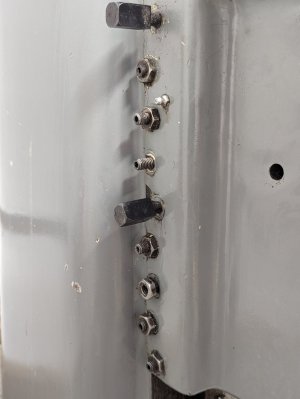
Pictured: ...like, you know, this stuff.

1000025748.jpg


The square-heads are the lock screws, I'm guessing...and the rest are probably adjusters of some sort, but I have no idea why they're in the positions they are. For that matter, I have no idea where the missing lock nut would be, or how at least three of them are doing anything at all insofar as pressure or load control is concerned.
 
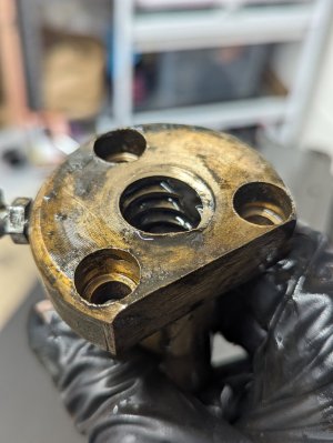
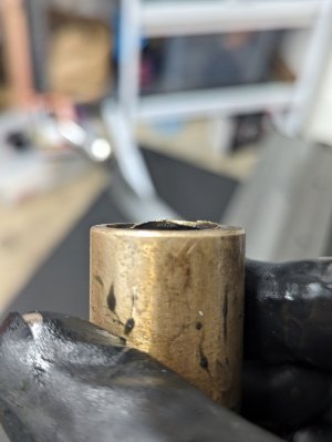
And a couple more bits of warpage to cap things off for the evening: the leadscrew nut.

Pictured: It's not supposed to look like this on the end, is it?

1000025746.jpg


Pictured: No...no, I don't think it's supposed to look like this.

1000025747.jpg


I don't think there's anything actually wrong, here; I think it's just unsightly. But, I can clean that up if I feel like doing so; it would be really easy with a mill...but I guess a file will do the trick.
 
Back
Top