Need help wiring Clausing 8520

JPigg55

Active User
H-M Supporter Gold Member
Joined
Nov 8, 2012
Messages
783
Trying to wire my Clausing 8520 for 220v. Previous owner had it wired for 110v.
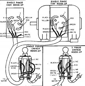
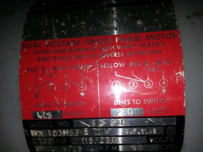
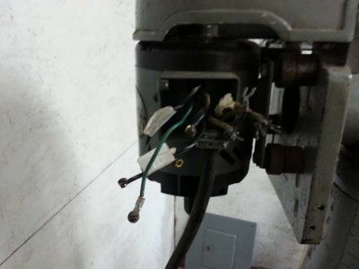
I've added pictures of the Clausing manual wiring diagram, motor wiring diagram, & motor wires.
I've wired the switch per the manual for 220v single phase, but when I got to the motor (wires had been disconnected for shipping by previous owner) none of the wire colors matched the manual or the motor wiring label.
The 4 wires coming out of the motor are: 1-Red, 2-Black with white stripe (both same color), and 1-Green. The green wire is a smaller gauge wire.
Previous owner labeld the wires as follows: 1-Red, 2-one of the Black with White stripe wires, & 3- the other Black with White stripe wires. As previously stated, it was wired for 110v.
How do I connect the wires and/or test the motor wires to figure out how to connect them ???
20131026_095723.jpg20131026_095551.jpgClausing 8520 wiring.jpg

20131026_095723.jpg 20131026_095551.jpg Clausing 8520 wiring.jpg
 
I had mine wired by a professional electrician. I will co down to the cave tomorrow and take pictures for you. I don't do any electrical work myself. It's the only thing I farm out.

"Billy G"
 
That motor appears to be a Delta or Rockwell motor which I would guess is not original equipment for a Clausing machine. Personally I would not depend on the diagram in the Clausing manual for motor connections. I would guess the green wire is a ground. Are you sure there aren't some other wires taped up and stuffed in the box you can't see?
 
That is a Rockwell / Delta motor . . . look on the motor tag and put the colored wires where indicated on the motor terminals for 220 volts . . .
 
NO, the tag is for the motor and Yes, I have a DMM and know how to use it.
The wiring part wouldn't be a problem except for figuring out which wire is which on the motor since the motor wires colors don't match the motor tag colors.
There are 4 wires coming out of the motor. One is a green, smaller guage wire than the other three that seems more like a ground fault wire to me, one red wire, and two wires that are black in color with a white stripe.
I know with 220v, you don't necessarily need a ground wire as with 110v and would then guess that one of the two black wires with the white stripe is the blue wire referenced on the tag.
That assumption being correct, I would then guess that one power lead connected to the B/WT wire and the other connected to the Blue would result in one direction of rotation and interchanging the B/Wt with the Red would result in the other direction of rotation.
Is there a way to test this with my DMM ???
 
JP.
The drawing that they had up is the one from the Clausing owners manual and it appears to be about as simple as it gets. I am "electrically" challenged and feel like I could get that to work if need be. Green is the standard for earth ground. Black with white stripes are coded as legs of a voltage. The red wire is either the cap or starter circuit switch. Some motors employ a cap to help them spin up, and others use a set of coils the are de-energized once the motor spins up to speed. use your DMM and measure the continuity to ground. One should be a dead short to ground and be green. The two black w/white shold show some resistance and be fairly close to each other in reading and the red wire will either show some resistance and hold or show a reading that diminishes to zero over time. Hope this helps, because that is about the sum total knowledge I have for electrical, but it should help you get er goin and enjoying some chip making too. Good luck and let us know how it works out.

Bob
 
Bad news for me. I think the motor is bad.
Resistance reading were as follows:
All wires to casing showed oper circuit, so green wire wasn't a ground fault wire.
Blk/W to Blk/W was 0.1 ohms and all others showed open circuit except Red to Green was fluctuating between 50 & 100 ohms for a short time before going open circuit (upon cliser inspection, Red wire shows severely cracked insulation and wire badly corroded).
Some good news is that I have another dual voltage, reverable motor with, I believe, the same shaft size and speed rating (will have to verify).
Bad news is that it's a 1.5 HP vs the 0.5 HP that's on the mill now.
Anyone foresee any problems with using the 1.5 HP motor ???
 
Yup, that motor is probably shot. I upgraded to a 1 HP on my 8520. It's more than enough.


"Billy G"
 
Bad news for me. I think the motor is bad.
Resistance reading were as follows:
All wires to casing showed oper circuit, so green wire wasn't a ground fault wire.
Blk/W to Blk/W was 0.1 ohms and all others showed open circuit except Red to Green was fluctuating between 50 & 100 ohms for a short time before going open circuit (upon cliser inspection, Red wire shows severely cracked insulation and wire badly corroded).
Some good news is that I have another dual voltage, reverable motor with, I believe, the same shaft size and speed rating (will have to verify).
Bad news is that it's a 1.5 HP vs the 0.5 HP that's on the mill now.
Anyone foresee any problems with using the 1.5 HP motor ???

Personally I would not be so quick to condemn that motor but I have been playing around with motors since I was about 12. If you don't feel comfortable working on it please pass that motor on to someone else who is rather than scrap it. I believe that is a Rockwell 62-610 and probably dates to the 1960's. If that is correct the shaft size is 1/2" and most probably will not match the 1.5hp motor. The mounting base will also probably not match.
 
On a positive thought a little extra oomph might be a good thing too. Going from 1/2 to 1 1/2 as long as you can bolt it up and aligh the pulleys is fine. You could even bore the pulley for a larger shaft or make a sleeve to go smaller. If it will run on 220 and switch directions it is a home run. Most of our small machines could use a bit more power, but that seems to be one of the places they cut short to save a little money. I would expect the motors to be physically larger in dialeter, but the important measurement is the shaft diameter and available length. You can always but a belt a tad longer or shorter once you get it mocked up and being assembled. I personally would not hesitate to adapt that motor if I could do it without making any permanent change to the basic machine. Motor plates and mounts are easy to drill and tap on the motors. Definately don't forget to post some pics up because according to the manual I ordered for the 8520 it originally was shipped in 1964 with no motor and you were supposed to supply one when you got the machine. They included the hardware and even the rubber grommets, but no motor on the originals.

Bob
 
Back
Top