Tool Post Grinder -Making a new one...

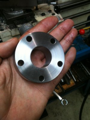
Actually... I been thinking about that a lot. If you look in there, I put a shoulder step in there to prevent the race from seating completely flat at the face. My initial thought was that a small gear puller mechanism could be used to pull it out. In hindsight, I've never seen a puller that small and would probably need to make something. -So only then, after I got a chance to lay eyes on it, did I start thinking about a couple screw holes.

I'm thinking screw holes would make life a lot easier but, I haven't researched the oil seals yet and don't know if they'll be large enough to cover-up the screw holes.

---Still thinking about this one... And I might just make a special tool to remove the race....


Ray

Just a thought, but have you considered putting a couple of holes through for bearing race removal?
 
Nice design and workmanship Ray. On the oil seals, in such a dirty environment, (grit from grinding) would a felt wiper be better? If grit gets under the felt it tends to impact into the felt where it won't score the shaft.

Greg
 
Here's the body piece, 1" wide. For an oil seal between the main pieces, I'll make a circular groove at the same radius on each mating surface then, I'll fill it with some permatex.

As for oil seals... If you look at the front piece, I made a groove for an O-ring and I'm still looking around for some proper oil seals. -Just haven't gotten around to it.

Indeed, I could put some holes in there to assist removing the race but, I'm leaning toward making a special puller. I made a step in there so the race won't seat totally flush and leaves room for the lip of a puller. We'll see...

Also, yes, I left room between the shaft and the opening in the housing to put a felt ring in there.

Finally, I'll have to work on the safety shield next. -Can't work on the 3rd piece of the body because the rear bearings have not arrived and I'm not cutting metal until they're in-hand and specd-out.

B1.JPG

Ray

B1.JPG
 
You could mill out a pair (or three, depending on your puller) relief arcs that would allow a deeper engagement of the puller jaws.
 
You could mill out a pair (or three, depending on your puller) relief arcs that would allow a deeper engagement of the puller jaws.


Wooo, now that's a good idea! I like that... I'll give it some good thought. Thanks!


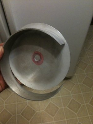
Now, for another matter... Wish me luck on this. I haven't TIG'd aluminum in a dog's age. Just tried a couple similar practice pieces and it took a while just to get the settings pretty close. -When will I remember to write these things down? I want this to look nice so, I'll practice a good bit before taking the plunge.

Anyhow, don't laugh too hard but, I do not own a metal roller bender so I bent this by hand over a pipe. It actually fits the circle pretty well. I sure hope I don't screw this up...

G1.JPG

Ray

G1.JPG
 
... The PDF should show the whole picture pretty clearly but, I did not include the wavy pressure spring that keeps the shaft and taper bearing under load...

PDF?

Don't you need that spring pressure to take-up the bearings' radial clearance?
 
Yes, it will be needed and it will be included. I didn't feel like spending the time to model the wavy-washer in CAD -and I couldn't find one in the parts library so, it wasn't included in the diagram (which I posted here as a PDF).

Ray


PDF?

Don't you need that spring pressure to take-up the bearings' radial clearance?
 
Sorry Ray, been busy with the Tool and Cutter Grinder, I missed the start of this. Looking good so far. When I open the files all I get is a white page with the title at the top?? Any ideas ??

"Billy G"
 
Last edited by a moderator:
Back
Top