E.J. Flather Mfg. Co. Automatic Gear Cutter

John, thank you for all the photos! I removed the arbor easily with your description. My release nut/handle is a bit different. Two of the studs are missing and one looks like it's soon to break. It did have a coat of never seize so it came apart easy. It will be an easy fix.

I didn't measure the taper, do you know way size it is? It looks like a Jarno #14, maybe?

IMG_3908[1].JPG
 
Is that the work arbor or the cutter arbor? On mine, I think the work arbor is #16 B&S and the cutter arbor is #3 Morse; I had to make it, but it has been to many years ago, I'd have to try it with a gage to be sure. I also made a new infeed nut, a 3 three start square thread, and a new bronze spindle bearing, which is tapered on the ID. Does your spindle housing adjust axially?
 
Is that the work arbor or the cutter arbor? On mine, I think the work arbor is #16 B&S

This is the work arbor. I ran back over to the shop and my quick measurements indicate it is a #14 B&S. I didn't think to check to see if it's sleeved down. I don't have the pattern gear cutting extension. Did you make that modification? I'll have to check if the spindle housing adjusts axially.
 
You may be right about the 14 B&S, I was working from memory, which at 74 is not what it was ----- I will post a pic of the axial adjustment later; does yours have the bracket for the cutter centering device? The shaft extension of pattern cutting is original on mine, I have not used it. I am supposing that is what it is for, I have no info on the machine. One thing that I remember is that the cutter speed change gears are on a non standard center distance, I had to reduce the pitch diameters to allow them to mount.
 
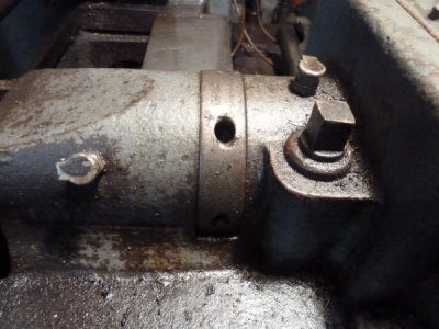
Here is the lateral adjustment, the ring with holes rotates, and being threaded onto the spindle housing moves the spindle and arbor laterally when rotated, using a round pin in the holes; the square bolt at the right locks the spindle housing in place; tightening too tight can cause binding of the bearing.

flather 3 001.JPG
 
Here is the lateral adjustment, the ring with holes rotates, and being threaded onto the spindle housing moves the spindle and arbor laterally when rotated, using a round pin in the holes; the square bolt at the right locks the spindle housing in place; tightening too tight can cause binding of the bearing.

Yes I have this adjustment. I was wondering what that was for... it looked well used so I figured it must have been important. :)
 
Yes, it is important, otherwise, you'd have to shim the cutters to center. BTW, I mailed off the indexing chart, etc. yesterday.
John
 
The little grey cells kicked in again! We had the discussion that the taper for the work arbors on mine, I thought it was #16 B&S, because I rebored it to that taper when a friend offered me 3 arbors with that taper, it would have been just like yours with the #14 when I got it. Did you receive the indexing sheets that I sent? Through looking at the pics of the seed/feed plate on yours, I realized that the feeds are not in inches per revolution as I thought, but Are definitely in inches per minute; I think I just had mine on a particular speed, and measured the feed. the feed box is driven by gearing from the input shaft, not the driven shaft that rotates the cutter.
 
Did you receive the indexing sheets that I sent? Through looking at the pics of the seed/feed plate on yours, I realized that the feeds are not in inches per revolution as I thought, but Are definitely in inches per minute; I think I just had mine on a particular speed, and measured the feed. the feed box is driven by gearing from the input shaft, not the driven shaft that rotates the cutter.

Your tables arrived today. THANK YOU! You put a LOT of work into those tables. With the tables I'm confident I can use this thing. Now I'm itching to find some time to tinker with it. I scanned them into a PDF and attached them here in the event will help anyone else. I hope that is OK.
 

Attachments

  • Flather_Gear_Cutter_12x30.pdf
    367.4 KB · Views: 3
I was lucky myself to find (before the internet) a copy of dividing table for a similar machine made by Brown & Sharpe I think that it used a worm gear of a different ratio, but re computing the table was an easy matter. I would still kike to see a better picture of the speed/feed plaque on your machine.
 
Back
Top