- Joined
- Jun 26, 2018
- Messages
- 1,733
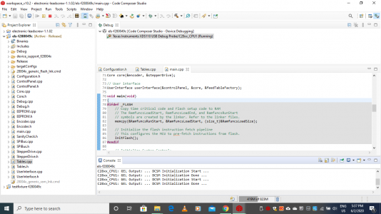
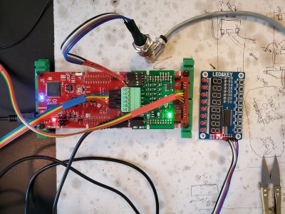
So if I understand @ttabbal you HAVE clough42's ELS? Can I hit you up for help? I ordered his board today, but looking through the 3 pages of many files....I have no idea WTH to do with them.The thing I like about the Clough42 system is that it is relatively simple. It tracks the spindle and moves the leadscrew to match. It is an electronic gearbox and doesn't try to be much more. You can add some things, but if you go much further you get into CNC land. This is a a manual machine that I don't have to fuss with change gears on. I didn't mind so much for threading, but I was already thinking of adding a variable speed drive for feed rates. He beat me to it and included threading in the mix.
I would like to see custom speeds and such, as well as using the power button to disable the driver. There is a patch out there for that, I just haven't taken the time to integrate it. Right now I go old school and flip the switch on a surge protector strip.