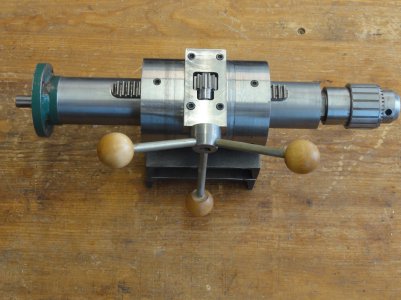
My woodworking was tending toward delicate pieces. I started thinking about a change of pace: something big, structural, imposing--a pagoda perhaps. I called this a gazebo when I talked to my wife about it. We know people who have those. It sounded more practical.
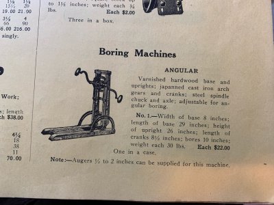
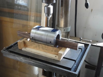
The timber joinery I’m thinking about uses wooden pegs or dowels, much bigger than any I’ve used. This would require a large drill, capable of boring precise holes 1” to 2” in diameter and up to 8” deep into the sides and ends of timbers up to 8” square. This will be made mostly out of stuff I had lying around, especially pieces of old production machines I had history with.
I started this in January. Most of the time I was pretty sure it wasn’t going to work. The axial alignment needed for the long travel of the drill worried me. There is actually nothing at all practical about this project; but, despite my misgivings, here it is: so far, so good.
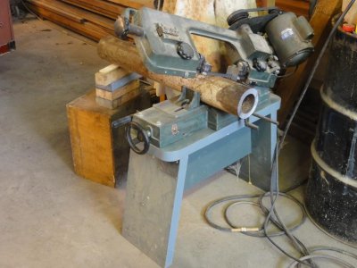
I started with this 4 ½” diameter heavy wall steel tube, old well casing, I think. I needed 6” off one end. My cut off saw was at this a while.
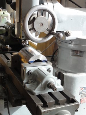
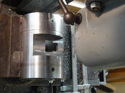
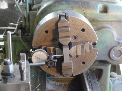
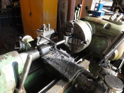
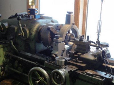
I turned the tube’s o.d. and set it up in a 4-jaw chuck and steady rest. I don’t have the ability to broach the large keyway needed for the gear rack that will move the quill, so I turned two plugs like the one on the lathe carriage. They have milled slots that will become the keyway when the plugs are pressed into counterbores in both ends of the tube.
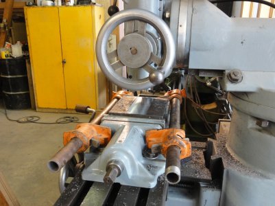
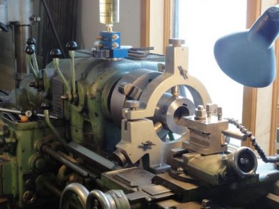
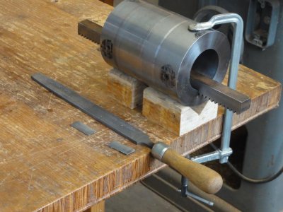
I planed a hardwood stick about 18” long to a snug fit in the slots and used it to align the two end plugs as they were pressed into the tube. They were bolted in place, and I was ready to finish bore the quill guide.
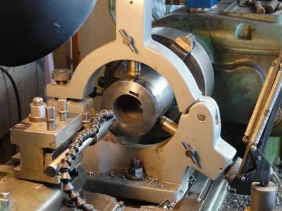
The depth of the keyway slots is about 0.020” shy of the o.d. of the quill bore. I thought I’d get a smoother, truer bore if it was an uninterrupted cut. My ability to grind a boring tool was much improved at this point.
A little work with a hack saw blade and a file cut out the two slivers of steel left across the gear rack slots.
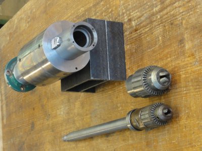
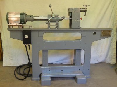
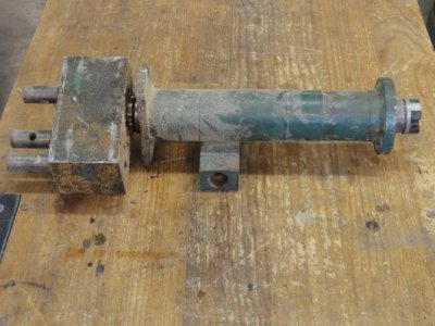
The quill is made from a drill drive shaft like this one off a patio door machine originally built in 1968. Sliding wood doors were built by the hundreds of thousands in those days. This was a heavy machine, built for continuous production, made just to cut the slots and holes for door rollers and locks. It ran until 1990. I rebuilt it in 1991 to install European mortise locks that were the latest thing then, and it continued working until 2000. I brought home a few components when it was scrapped.
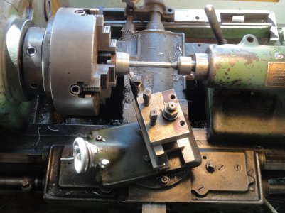
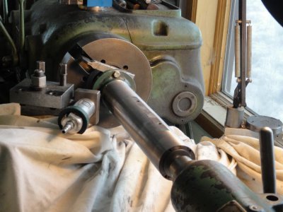
I turned plugs for the bearing bores at either end of the tube so I could mount it between centers and turned the o.d. I set an indicator against the tailstock and budged it a thousandth or so to get the same o.d. at both ends, but there was a slight, barely detectable, bulge in the middle. The quill slid into the bore about 1/3 of the way and stopped cold. A little blue layout dye found the exact spot. I was able to feed the grinder in at that point and just skim the center portion of the quill.
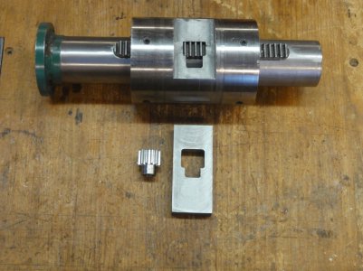
The fitted quill went over to the milling machine to get a slot for the gear rack.
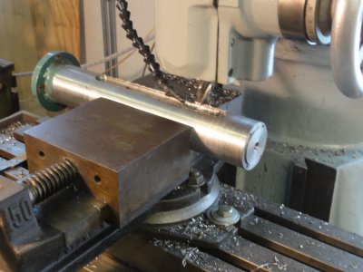
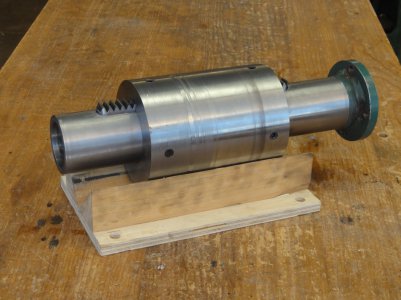
I milled down the rack a bit and set in into the quill with 3 cap head bolts from the back side. I worked the stiffness out by sliding it back and forth a few times by hand to burnish the machined bore with the ground quill.
The timber joinery I’m thinking about uses wooden pegs or dowels, much bigger than any I’ve used. This would require a large drill, capable of boring precise holes 1” to 2” in diameter and up to 8” deep into the sides and ends of timbers up to 8” square. This will be made mostly out of stuff I had lying around, especially pieces of old production machines I had history with.
I started this in January. Most of the time I was pretty sure it wasn’t going to work. The axial alignment needed for the long travel of the drill worried me. There is actually nothing at all practical about this project; but, despite my misgivings, here it is: so far, so good.

I started with this 4 ½” diameter heavy wall steel tube, old well casing, I think. I needed 6” off one end. My cut off saw was at this a while.

I turned the tube’s o.d. and set it up in a 4-jaw chuck and steady rest. I don’t have the ability to broach the large keyway needed for the gear rack that will move the quill, so I turned two plugs like the one on the lathe carriage. They have milled slots that will become the keyway when the plugs are pressed into counterbores in both ends of the tube.

I planed a hardwood stick about 18” long to a snug fit in the slots and used it to align the two end plugs as they were pressed into the tube. They were bolted in place, and I was ready to finish bore the quill guide.

The depth of the keyway slots is about 0.020” shy of the o.d. of the quill bore. I thought I’d get a smoother, truer bore if it was an uninterrupted cut. My ability to grind a boring tool was much improved at this point.

A little work with a hack saw blade and a file cut out the two slivers of steel left across the gear rack slots.

The quill is made from a drill drive shaft like this one off a patio door machine originally built in 1968. Sliding wood doors were built by the hundreds of thousands in those days. This was a heavy machine, built for continuous production, made just to cut the slots and holes for door rollers and locks. It ran until 1990. I rebuilt it in 1991 to install European mortise locks that were the latest thing then, and it continued working until 2000. I brought home a few components when it was scrapped.

I turned plugs for the bearing bores at either end of the tube so I could mount it between centers and turned the o.d. I set an indicator against the tailstock and budged it a thousandth or so to get the same o.d. at both ends, but there was a slight, barely detectable, bulge in the middle. The quill slid into the bore about 1/3 of the way and stopped cold. A little blue layout dye found the exact spot. I was able to feed the grinder in at that point and just skim the center portion of the quill.

The fitted quill went over to the milling machine to get a slot for the gear rack.

I milled down the rack a bit and set in into the quill with 3 cap head bolts from the back side. I worked the stiffness out by sliding it back and forth a few times by hand to burnish the machined bore with the ground quill.


