Has anyone made a zeroing sensor to control a relay when a cutter touches a metal plate?
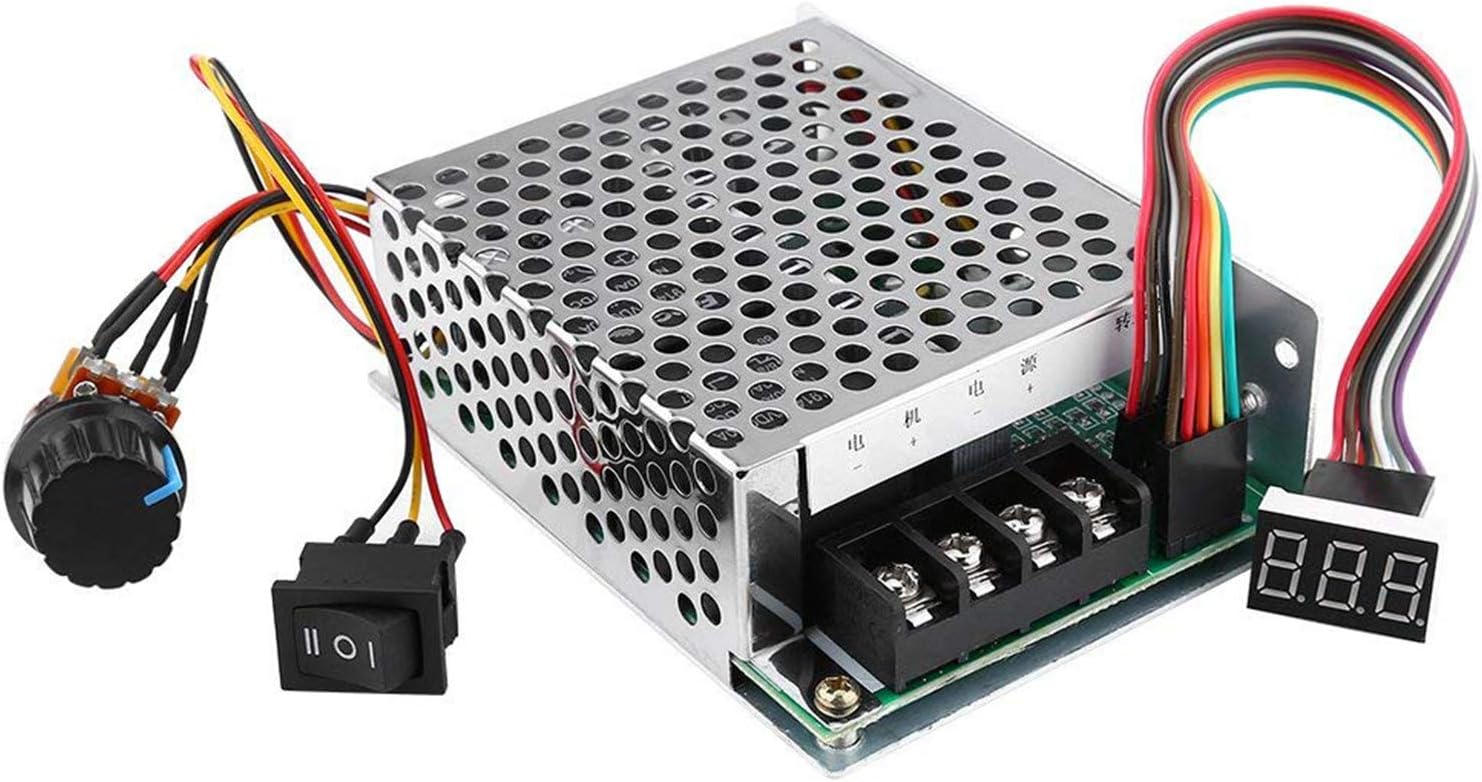
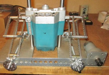
I'm in the planning stages of building a motorized router lift & I'm curious if there's something that can be used to stop a 24V DC gearmotor once the cutter touches a flat brass plate?
I'm planning to use a i Gauging EZ View for the readout, So once I know the bit is level to the top-plate I can just zero out the display.
Something as simple as This Touch Sensor controlling a relay may work?
However something like the Arduino & Sensor used in this YouTube Video along with a relay may work a little better since you can adjust the sensitivity?
Doug