- Joined
- Dec 20, 2021
- Messages
- 868
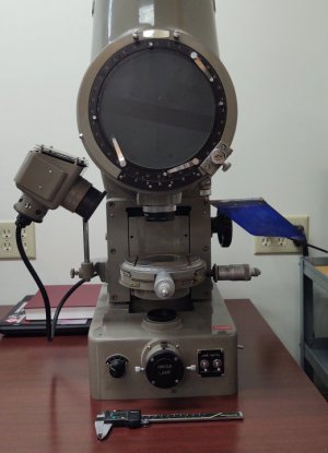
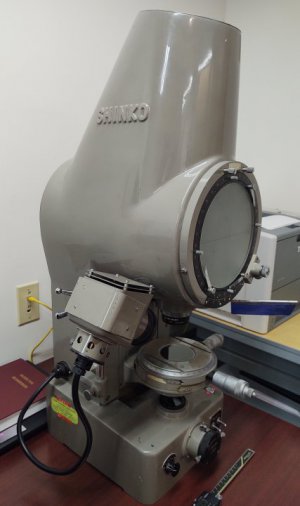
This project started out as a 'wish list' find. An 8" bench top optical comparator, which of course needed bulbs. Given that bulbs are impossible to find and expensive, an LED upgrade was eminent.
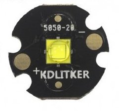
The first step was to identify the LED. The filament in these style bulbs are designed to provide a 'flat plane' of light, in the case of this bulb the filament covered approximately 3mm by 3mm. This is an exact match with the die area of many common 5mm LED's. The Cree XM-L3 was settled on, as it has a 3mm by 3mm die. The big thing with the XM-L is that it's a single die making, light over the whole 3mm by 3mm surface. The LED light output is overkill (70W bulb is probably a few hundred lumens, where the XM-L3 is around 1800 lumens max). These were sourced soldered on 20mm stars, from kaidomain. This image was sourced from the kaidomain web site.
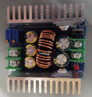
The LED Drivers were more of a pain. Most flashlight drivers are small and hard to mount. So, I sourced some of the larger DC-DC modules on line (amazon, ebay, etc). It turns out this might have been a mistake. LED's need to be powered with a constant current power supply which these supplied claimed. These DC-DC modules claimed to operate in CC mode, and they did, sort of. The plan was to mount the constant current adjustment remotely from the board, where the light bulb voltage selector was.
Testing the power supply is where the trouble started. These did a horrible job regulating current. Being an EE by trade a good old reverse engineering was done. It turns out the implementation wasn't just bad, it was downright horrible. There are so many things done poorly, I almost threw them in the trash and started from scratch. After reverse engineering the schematic, I did what any other cheapskate would do; Modify them to work as needed. The bottom line is that after several days, a few modifications to the board (and very small parts) would allow these supplies to operate as adjustable constant current sources. They allow LED current from 250mA to the maximum 5A needed by the LED's. (I'll include details on the on the modifications below).
Next was the LED mount. For those not familiar with LED's they differ from light bulbs in one significant way; They need to run cool, where light bulbs run hot. The LED mount needs to cool the LED as much as hold it in place. LED's are typically mounted to copper based circuit boards (star) that have thin copper surface traces for power. The copper is a heat spreader that gets mounted to a heat sink. The LEDs don't need to be dead cold, but the cooler they run the better.
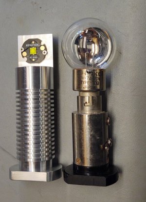
The original contour light mount was removed, and a replacement aluminum mount was designed. Keep in mind, the contour light needs to be culminated, that is all of the light 'rays' should be parallel to each other. The lower focusing lens is a culminating lens that takes the 'cone of light' from the source and culminates it to parallel rays. This lens is comprised of multiple lenses (I know I had to disassemble it for cleaning!). The location of the light source is also critical. The mount was designed to reproduce the X,Y, and Z, positions as well as being square in all planes of the original filament. (This comparator allows for some X,Y, and Z adjustment, so exact duplication isn't needed but closer is better). Fortunately the bulb mount was rather large, and allowed the use of a big chunk of aluminum for heat sinking.
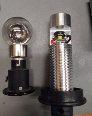
The next step was to repeat the process with the surface light. The lens there doesn't appear to be a culminating lens, but alignment it probably more critical as there is no X,Y, or rotation adjustment. This location was duplicated very closely. This lens does have some ability to focus, making the LED die spot focus from very small to very large. If the die isn't in the right location focus won't help get you there. So this mount was probably more critical than the contour light.
After all that, a quick test was done with contour and surface LED's. Once they were working the existing wiring was pulled out of the comparator, and the DC-DC modules were mounted on the original transformer mount. The 'brigtness' control potentiometer chosen was a dual ganged pot, so it adjusts brightness of both LED's at the same time. Other than an hour of wiring, the last major issue was DC power for the DC-DC drivers. Last minute the decision was made to power this off a 24V wall wart, so no AC power would exist inside the unit. The power plug was replaced with an aluminum mount holding a standard barrel connector.
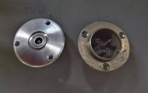
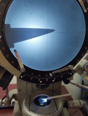
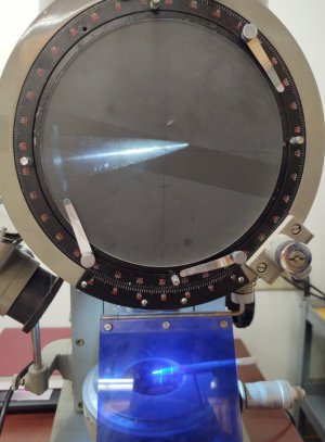
Overall I'm pretty happy with the upgrade. It works well, and a check with a gauge block shows it to be very accurate. This is only a 10x comparator, and being 8" it won't work for big parts. But for small lathe cutters, or checking the torx drive features I mill into #2-56 screws it will work fine. The biggest thing was that from the outside (other than the power connector) everything is original. The same power cable was used for the surface lamp, and all the switches and knobs were reused. I wanted to keep that 'vintage' 1980's look and feel. Other than needing a good cleaning, it appears to be in pretty good shape. Here's a couple of shots of a lathe cutter (very worn out) and the printing on that same cutter with the surface light. (FYI, It's hard to get a good shot with a cell phone.
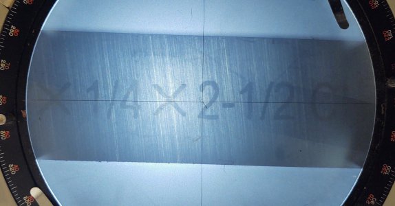
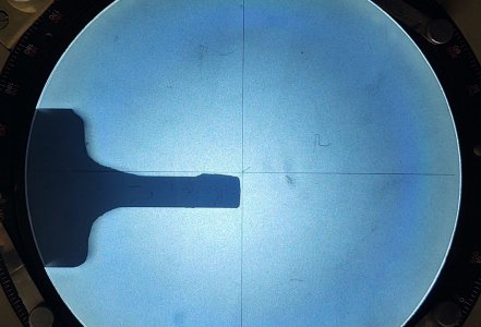
Hopefully this helps anyone wanting to do an LED upgrade. Other than the LED driver, it's pretty basic machining and wiring.
Dan
P.S. For the TLDR on the LED supply upgrade, continue on.
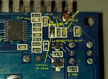
The modifications are relatively simple (for those unafraid to solder 0603 surface mount components). The mods basically turn this CV/CC supply
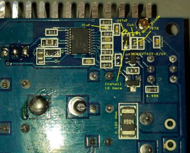
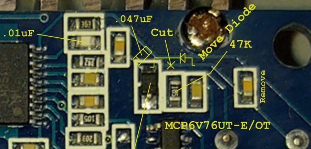
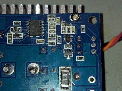
to a CC/CV supply. (Emphasis on CC mode). See attached images for details on mods to be done.
In the control loop for constant current there was a diode to separate CC and CV modes. That diode was moved from the CC feedback loop into the voltage feedback. After doing this the supply was not properly compensated and would tend to oscillate, so a few of the values setting loop bandwidth needed to be changed. With this done, the supply has good control over the constant current setting, but poor constant voltage. Of course being a LED driver now, we don't care.
A new OP-AMP was used for the current sense opamp, MCP6V76UT-E/OT from microchip. This opamp is a low drift opamp, where the existing LM321 is not. Not may choices exist in this footprint in this package. (This Footprint is common in SOT-70, Not SOT-23). Note the opamp is a 5 pin part, even though there are 6 pins on the board. Pay attention to the orientation.
Once the changes are made, Current operating point can be set with the CC potentiometer. (I wired this external to the board for hand
control, but this will tend to make the supply oscillate if that wire is long or routed poorly).
The maximum current can be trimmed with the CV POT. Adjusting this pot with the LED Load and a Current Meter monitoring the output will
trim the feedback circuit such that the maximum current is limited. In tests done with this board, the target was shifted from 3.0A to 5.0a maximum.
Note, however the .160 Ohm resistor used is is only rated for 2W. At higher currents, a higher wattage resistor may be needed. But honestly, 5A at 1800 Lumens is just too stupid bright to be useful, especially on the contour light. The surface light might benefit from more current however.
For the brave, the rest of the images show how to do the mods.
The first step was to identify the LED. The filament in these style bulbs are designed to provide a 'flat plane' of light, in the case of this bulb the filament covered approximately 3mm by 3mm. This is an exact match with the die area of many common 5mm LED's. The Cree XM-L3 was settled on, as it has a 3mm by 3mm die. The big thing with the XM-L is that it's a single die making, light over the whole 3mm by 3mm surface. The LED light output is overkill (70W bulb is probably a few hundred lumens, where the XM-L3 is around 1800 lumens max). These were sourced soldered on 20mm stars, from kaidomain. This image was sourced from the kaidomain web site.

The LED Drivers were more of a pain. Most flashlight drivers are small and hard to mount. So, I sourced some of the larger DC-DC modules on line (amazon, ebay, etc). It turns out this might have been a mistake. LED's need to be powered with a constant current power supply which these supplied claimed. These DC-DC modules claimed to operate in CC mode, and they did, sort of. The plan was to mount the constant current adjustment remotely from the board, where the light bulb voltage selector was.

Testing the power supply is where the trouble started. These did a horrible job regulating current. Being an EE by trade a good old reverse engineering was done. It turns out the implementation wasn't just bad, it was downright horrible. There are so many things done poorly, I almost threw them in the trash and started from scratch. After reverse engineering the schematic, I did what any other cheapskate would do; Modify them to work as needed. The bottom line is that after several days, a few modifications to the board (and very small parts) would allow these supplies to operate as adjustable constant current sources. They allow LED current from 250mA to the maximum 5A needed by the LED's. (I'll include details on the on the modifications below).
Next was the LED mount. For those not familiar with LED's they differ from light bulbs in one significant way; They need to run cool, where light bulbs run hot. The LED mount needs to cool the LED as much as hold it in place. LED's are typically mounted to copper based circuit boards (star) that have thin copper surface traces for power. The copper is a heat spreader that gets mounted to a heat sink. The LEDs don't need to be dead cold, but the cooler they run the better.
The original contour light mount was removed, and a replacement aluminum mount was designed. Keep in mind, the contour light needs to be culminated, that is all of the light 'rays' should be parallel to each other. The lower focusing lens is a culminating lens that takes the 'cone of light' from the source and culminates it to parallel rays. This lens is comprised of multiple lenses (I know I had to disassemble it for cleaning!). The location of the light source is also critical. The mount was designed to reproduce the X,Y, and Z, positions as well as being square in all planes of the original filament. (This comparator allows for some X,Y, and Z adjustment, so exact duplication isn't needed but closer is better). Fortunately the bulb mount was rather large, and allowed the use of a big chunk of aluminum for heat sinking.

The next step was to repeat the process with the surface light. The lens there doesn't appear to be a culminating lens, but alignment it probably more critical as there is no X,Y, or rotation adjustment. This location was duplicated very closely. This lens does have some ability to focus, making the LED die spot focus from very small to very large. If the die isn't in the right location focus won't help get you there. So this mount was probably more critical than the contour light.

After all that, a quick test was done with contour and surface LED's. Once they were working the existing wiring was pulled out of the comparator, and the DC-DC modules were mounted on the original transformer mount. The 'brigtness' control potentiometer chosen was a dual ganged pot, so it adjusts brightness of both LED's at the same time. Other than an hour of wiring, the last major issue was DC power for the DC-DC drivers. Last minute the decision was made to power this off a 24V wall wart, so no AC power would exist inside the unit. The power plug was replaced with an aluminum mount holding a standard barrel connector.

Overall I'm pretty happy with the upgrade. It works well, and a check with a gauge block shows it to be very accurate. This is only a 10x comparator, and being 8" it won't work for big parts. But for small lathe cutters, or checking the torx drive features I mill into #2-56 screws it will work fine. The biggest thing was that from the outside (other than the power connector) everything is original. The same power cable was used for the surface lamp, and all the switches and knobs were reused. I wanted to keep that 'vintage' 1980's look and feel. Other than needing a good cleaning, it appears to be in pretty good shape. Here's a couple of shots of a lathe cutter (very worn out) and the printing on that same cutter with the surface light. (FYI, It's hard to get a good shot with a cell phone.


Hopefully this helps anyone wanting to do an LED upgrade. Other than the LED driver, it's pretty basic machining and wiring.
Dan
P.S. For the TLDR on the LED supply upgrade, continue on.
The modifications are relatively simple (for those unafraid to solder 0603 surface mount components). The mods basically turn this CV/CC supply
to a CC/CV supply. (Emphasis on CC mode). See attached images for details on mods to be done.
In the control loop for constant current there was a diode to separate CC and CV modes. That diode was moved from the CC feedback loop into the voltage feedback. After doing this the supply was not properly compensated and would tend to oscillate, so a few of the values setting loop bandwidth needed to be changed. With this done, the supply has good control over the constant current setting, but poor constant voltage. Of course being a LED driver now, we don't care.
A new OP-AMP was used for the current sense opamp, MCP6V76UT-E/OT from microchip. This opamp is a low drift opamp, where the existing LM321 is not. Not may choices exist in this footprint in this package. (This Footprint is common in SOT-70, Not SOT-23). Note the opamp is a 5 pin part, even though there are 6 pins on the board. Pay attention to the orientation.
Once the changes are made, Current operating point can be set with the CC potentiometer. (I wired this external to the board for hand
control, but this will tend to make the supply oscillate if that wire is long or routed poorly).
The maximum current can be trimmed with the CV POT. Adjusting this pot with the LED Load and a Current Meter monitoring the output will
trim the feedback circuit such that the maximum current is limited. In tests done with this board, the target was shifted from 3.0A to 5.0a maximum.
Note, however the .160 Ohm resistor used is is only rated for 2W. At higher currents, a higher wattage resistor may be needed. But honestly, 5A at 1800 Lumens is just too stupid bright to be useful, especially on the contour light. The surface light might benefit from more current however.
For the brave, the rest of the images show how to do the mods.


