

-
Welcome back Guest! Did you know you can mentor other members here at H-M? If not, please check out our Relaunch of Hobby Machinist Mentoring Program!
You are using an out of date browser. It may not display this or other websites correctly.
You should upgrade or use an alternative browser.
You should upgrade or use an alternative browser.
Anyone read japanese?
- Thread starter Mikinvt
- Start date
- Joined
- Nov 14, 2020
- Messages
- 1,761
Show a picture of the terminals in the motor box.
This is not that hard.
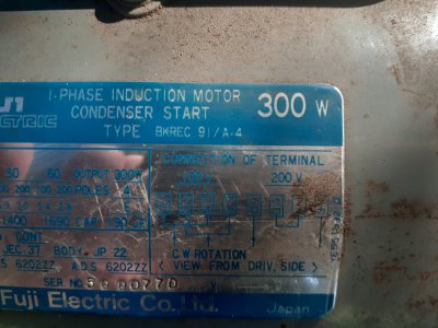
You will use the 100 v chart on left of the right side of the label.
The terminals should be laid out just as the drawing, there is only two wires and two jumpers.
This is not that hard.
You will use the 100 v chart on left of the right side of the label.
The terminals should be laid out just as the drawing, there is only two wires and two jumpers.
- Joined
- Apr 30, 2015
- Messages
- 11,343
It should be possible to ring out the winding pairs without needing to read Japanese- post a pic of wire box
The unit will run a bit warm on 120V but should be OK for short periods of lathe use
-M
The unit will run a bit warm on 120V but should be OK for short periods of lathe use
-M
- Joined
- Apr 29, 2019
- Messages
- 2,066
Google translate on an android phone is supposed to be able to translate Japanese writing to English. You may have to mess around some with different lighting to get enough contrast for the translator to make out the characters.
How is it currently wired?
Does it just have wires or are there terminals to connect to?
A pic of the inside of the box would be most helpful here.
Are the wires or terminals marked with those Japanese characters? since the rest of the plate is in English?
You know that the 2 outside wires are line and neutral
.
If the other two are connected together than you know it is wired for 220.
If there are 2 jumpers then it is already wired for 100.
It looks like this motor is clockwise only so you are good there.
If it is wired for 220 then remove the jumper, and your ohm meter will tell you which terminals are the ends of one winding. For 100V the windings are connected in parallel and for 220 the windings are in series.
Pay attention to motor heat, it is a 100V motor that you will be feeding 120. That is a 20% increace over design voltage. Where I work we have different windings for 100 V vs 120V. a 100V motor will run hot on 120,
- Joined
- Feb 2, 2013
- Messages
- 3,629
i run 100v motors on 120V all the time on conveyor systems
there is a nominal rise in temperature, but i have not had thermal failures as a result
there is a nominal rise in temperature, but i have not had thermal failures as a result
- Joined
- Apr 29, 2019
- Messages
- 2,066
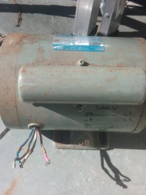
OK that pic helps a lot. Now if you can tell us which markings are on what color......
I am pretty sure I now what connections you need to make but the color to marking info combined with that 200V hand drawn diagram on the side of the motor will confirm my thoughts. It can also be verified with an ohm meter.
I am pretty sure I now what connections you need to make but the color to marking info combined with that 200V hand drawn diagram on the side of the motor will confirm my thoughts. It can also be verified with an ohm meter.
Blue u2 black v1 white u1 and red v2OK that pic helps a lot. Now if you can tell us which markings are on what color......
I am pretty sure I now what connections you need to make but the color to marking info combined with that 200V hand drawn diagram on the side of the motor will confirm my thoughts. It can also be verified with an ohm meter.
- Joined
- Apr 30, 2015
- Messages
- 11,343
Probably black and white together and blue and red together; connect those two pairs to power 120V
Good chance of working- reversing direction should be possible by swapping black and red
-Mark
Good chance of working- reversing direction should be possible by swapping black and red
-Mark
Last edited:
- Joined
- Feb 1, 2018
- Messages
- 1,868
Rex Walter a member on here lives in Japan. He is married to a Japanese lady. I know he is fluid in the language, so I bet he could translate it. I emailed him, so hopefully he will see it soon.
Rich
Rich