VN Van Norman No. 12 oil cup questions

John TV

Registered
Registered
Joined
Mar 15, 2016
Messages
238
So the second set of questions for all you VN guys and gals is about the oil cups and daily oiling of machine.

Cal and others, already gave me info on the lube for the 3 gearboxes,and what grease to use with the electric motors, and recommended vactra way oil for the oil cups and other oiling.

So I studied the old operating manual I have from Vintage Machine Shop and the parts diagrams (very grainy) and even the old sales brochure, and unless I missed it, none of those actually say or show where the oil cups are located.

From looking at my "new" VN12 it looks like there are 8 or 9. Here is what I think I have. Pics are below.
Oil cups or buttons:
1..Back of machine Ram screw
2/3/4. Back of table for ?ways?
5. Front of table button for?
6. Right side x axis bearing (missing hand wheel)
7. Y axis oiler
8. Z axis knee oiler
9. Right side under table for auto feed maybe?
Do you know if I am missing any?
I don't see any cup for the left side of x axis at all?

As mentioned in previous threads I am very new to this and have been brushing oil on lead screws visible pasts of ways etc. is this overkill?

As always you folks rock. Any help or advice is most appreciated.

John V. Minnesota

a88ed5f073e4f1c442dd3c1efd5fe3d7.jpg

c5a5ed30d6e6f9208295a1f9f0e14bbb.jpg
cb4f3df85150b6ff187d1186da194bae.jpg

9d320b2f2be330c8c5528c1345595319.jpg

2b3a710a766f7d35c6164a0852721350.jpg

722cc836e9363fac909a52bbfdb7fcc3.jpg


Sent from my iPhone using Tapatalk
 
Last edited by a moderator:
I did not explain or show cups 2/3/4 very well.

On the back side of the table I have one oil cup ( pick below) and two " holes" where it looks like oil cups once lived but were broken off. Are these other two holes truly
c81731b11ac7491066f845f5dcd3e79b.jpg

550585666567386613968193ef794420.jpg
oil cup holes? ( only show 1 in pick)


Sent from my iPhone using Tapatalk
 
Make sure to replace any and all missing oilers and any that are damaged, like the ones I see with the caps missing. The caps are there to keep the grit and swarf out of the working parts of the machine. The caps need to fit and close properly. In the meantime, putting oil on the ways and other places you can reach is a good idea. Don't procrastinate. Lack of clean lubrication kills machines quickly.
 
I agree. My opinion, is that for a home / hobby machine that is not made anymore, there is no possibility of too much lube. It may be a tad messy, but much better then wearing out your machine.

I also feel its better to decrease the lube interval (Lube more often) from the factory recommended intervals, as the machine wears/ ages.
 
As mentioned above, err on the generous side until you get a feel for how often to oil based on your experience with the machine.
 
...

So I studied the old operating manual I have from Vintage Machine Shop and the parts diagrams (very grainy) and even the old sales brochure, and unless I missed it, none of those actually say or show where the oil cups are located.

From looking at my "new" VN12 it looks like there are 8 or 9. Here is what I think I have. Pics are below.
Oil cups or buttons:
1..Back of machine Ram screw
2/3/4. Back of table for ?ways?
5. Front of table button for?
6. Right side x axis bearing (missing hand wheel)
7. Y axis oiler
8. Z axis knee oiler
9. Right side under table for auto feed maybe?
Do you know if I am missing any?
I don't see any cup for the left side of x axis at all?
...
Hi John,

Sorry about not responding sooner. There's a lot to say on this subject and I've been trying to find time to get to it. I'll try to do it in installments.

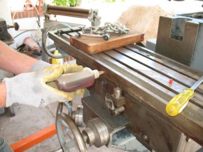
There are over 20 places that need lubrication with way oil. You're missing two important ones, the ones for the X and Y ways. The one for the table ways is on the front of the table itself, near the middle:
IMG_9249.jpg
You should see oil coming out on the sides of the saddle, below the ways in front and in back. If not, something is plugged up.

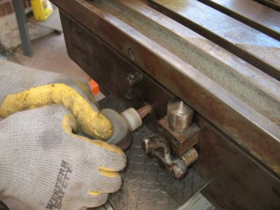
The oil point for for the Y-axis (saddle) is on the front of the saddle, to the left of the feed control:
IMG_9251.jpg
Oil should come out on top of the knee, in front and behind the saddle. If not, the oil passage is probably plugged you you'll need to pull the knee to clear it.

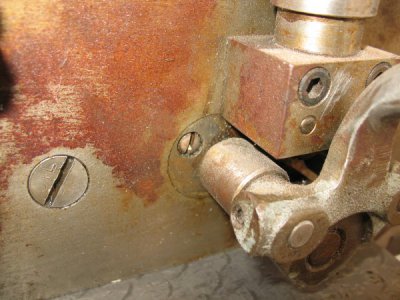
The above oil locations are covered with slotted screws that have the word "OIL" stamped on them.
IMG_9232.jpg

You should put oil in these points every time you use the machine. I'll try to get to more of this later.
 
I did not explain or show cups 2/3/4 very well.

On the back side of the table I have one oil cup ( pick below) and two " holes" where it looks like oil cups once lived but were broken off. Are these other two holes truly oil cup holes? ( only show 1 in pic)
c81731b11ac7491066f845f5dcd3e79b.jpg

550585666567386613968193ef794420.jpg

...
No. There's only one oil cup at that level. The other two holes have plugs for cross-drilled holes.

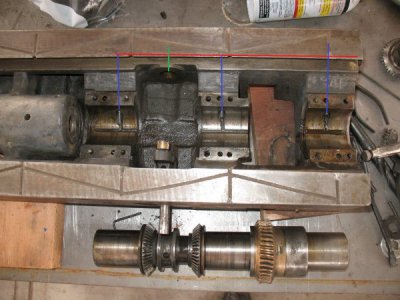
The oil cup shown in the first photo, above, located high on the (operator's) right-rear of the saddle, feeds oil to the four sleeve bearings for the table feed gears. This annotated photo should help understand what's going on:
IMG_8709ra.jpg

The red line is a long, horizontal hole drilled in the back of the saddle. It serves to channel oil to three of the four bearings. If you look on the right side of the saddle, below the rear way, you'll find a screw plugging the right end of the hole. The three blue lines mark the location of three holes, drilled downwards at an angle, that carry oil from the red horizontal passage to the three large sleeve bearings that are concentric with the leadscrew. The passage for the bearing on the right extends upwards to the oil cup itself, which supplies oil to all four bearings (as previously stated). The middle and left-hand blue lines are the locations of the two screws which cap off the upper ends of the passages (like the one shown in the second photo, above).

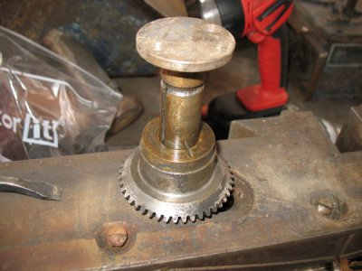
The green line indicates the oil channel for the table feed reverse idler gear (the idler gear is not shown in the above photo). If you look at the back of the saddle, about in the middle, you'll find a disk with two screws; this is the end of the stub shaft that the idler gear runs on. This photo shows the stub shaft [12-585], spacer [12-584] and idler gear [12-491]. (The numbers in brackets are the Van Norman part numbers for the indicated parts.):
IMG_8706.jpg
The screws capping two of the blue cross-drill holes, mentioned above, are also visible in this photo.

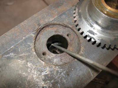
The top of stub shaft hole in the apron intersects the red horizontal oil passage, as shown in this photo:
IMG_8708.jpg

The pointer, above, indicates the oil passage where it intersects the stub shaft. Radial and horizontal grooves in the stub shaft carry oil to the sleeve bearing [12-412] pressed into the idler gear. Note that the idler gear simply floats on the end of the stub shaft, with the spacer keeping it in proper mesh with the other two gears. Excess oil from the gear bearing oil system goes into the center well for the bevel gears or drips into the cover [12-391] underneath the feed worm-wheel carrier [12-471]. Excess oil from the lubrication point on the front of the table also winds up in the center sump or worm-wheel cover.

An important point that's frequently missed is that the center sump is meant to be filled with oil, otherwise the bevel gears will run without lubrication. It's not uncommon to find the sump either dry or packed with a combination of grease/oil/swarf. One thing that should always be done with a newly acquired Van Norman No. 12 is to remove the table (or at least move it far enough to the left to expose the bevel gears) so that the gears can be cleaned, inspected and the sump filled with oil.
 
Ok, my newby head hurts just a little bit now trying to absorb just a fraction of your knowledge. I am blown away by your knowledge and your willingness to spend the time to help me ( and likely others) understand at a level of text book excellence. Thank you! I will totally understand if you get tired of my ongoing questions. I know I would never have gained this knowledge without your help.

Ps, I drained, flushed and filled with your recommended oil the spindle, feed gear box and ram gear box and I was amazed at how little oil there was and how dirty it was. I also found I need to make a new gasket for the feed gear box cover. Leaked like a sieve with the gears spinning.

Now on to finding the sump


Sent from my iPhone using Tapatalk
 
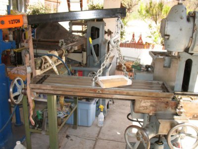
As I said, the best way to go is to remove the table. What I've done in the past is support it using an engine hoist, a length of chain and a couple of bolts and T-nuts:
IMG_8991.jpg
You could probably also use some sort of cart or table to support it as you slide it off. Be careful that you support it fully so you don't damage the saddle as it comes off the end. You can use the leadscrew to push it to the left until it's about half way off.

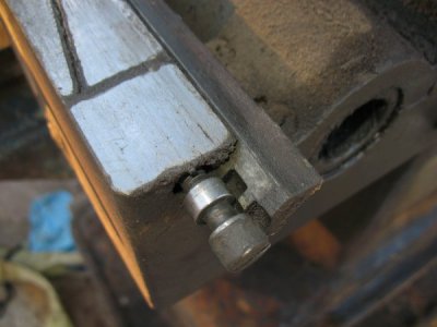
Loosen (or remove) the gib before you start and take the gib out before you go past the center. Back off the screw on the right side to loosen and withdraw the gib from the right. Here's what the right end of the gib looks like (with the table off and the screw backed way out):
IMG_8242.jpg
 
Back
Top