1957 Logan with no QCGB, What do you think of electronic controlled lead screws?

Jon In Tucson

Active User
Registered
Joined
Apr 13, 2014
Messages
82
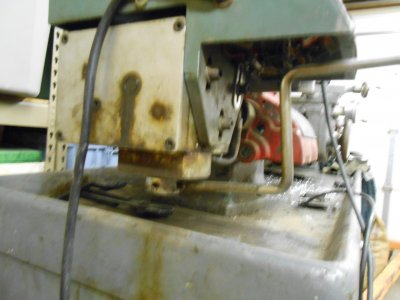
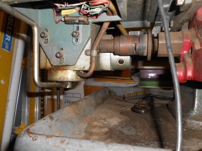
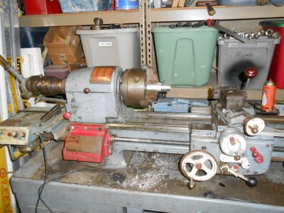
Well, just as the title says my son and I have aquired a Logan 1957 lathe. In its previous life the QCGB had been gutted and a direct drive electric motor installed to power the lead screw. There is a variable speed dial and a forward/reverse lever on the gear motor. Also in the deal, we got a 6 position turret and a 5C quick change collet. Our goal is to be able to do a few hobby gunsmithing chores such as chamber, crown barrels, as well as thread barrels.
After some online research on cost and availability of a replacement QCGB, I met the Chance brothers, Slim and None...:banghead: So now I have looked at the possibility of a electronically controlled lead screw. I understand the theory as to how it operates and am not afraid to tackle such a project. Have any of you done such a thing? Is the accuracy comparable to the mechanical gearset found on a lathe or am I just blowing smoke?
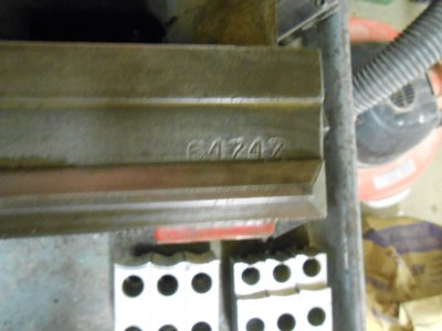
Here are a few pictures of our diamond in the rough. Thanks for your input and God bless.
Jon In Tucson
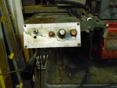
011.JPG 008.JPG 009.JPG 010.JPG 013.JPG
 
I have never seen a drive system like that. Looks like it was made in the 60's or so.

To answer your question, yes it is possible to do what you want. In fact it looks like you already have that, kind of.

You could drive the leadscrew with a stepper or servo motor. That would give you a range of speeds, but you should already have that, assuming the current system is operational.

The problem would be threading. In that case you would have to know the rotational position of the spindle in relation to the carriage. This could be done with an encoder driven by the spindle, and a scale on the carriage. That data would be fed to the controller that would then calculate the proper position of the leadscrew and command the drive motor. Electronically controlled, you could cut any thread you wanted.

If you take a look at the Mach3 forum, you might find someone that has done this. I have seen CNC lathe conversions so I know it has been done.

As far as the accuracy, it should be just as good or better than the original QCGB

Use an encoder on the spindle and another on the leadscrew. Then the controller just needs to do the same math the gearbox did. I'd use a dc motor (sounds like you've already got one) rather than a stepper: you want smooth motion. You need to control phase as well as speed so that you can get back to the same place.
 
Use an encoder on the spindle and another on the leadscrew. Then the controller just needs to do the same math the gearbox did. I'd use a dc motor (sounds like you've already got one) rather than a stepper: you want smooth motion. You need to control phase as well as speed so that you can get back to the same place.


I am not a real fan of reading position from a lead screw, even a ball screw. It tends to introduce errors into the system due to backlash, wind up, and end play. If I have a choice I will always read the position of the final device that you want to position. In this case the carriage, or in the case of a mill, the table. It is my preference to let the controller figure out the best way to achieve the position.

I agree that a DC motor may give smoother operation than a stepper, but on the other hand, a good step motor controller will operate up 20,000 steps per revolution. That pretty much takes the lumps out of it.

DC motor and step motor systems each have their strong points and weaknesses. Ultimately the application and the end users budget will dictate the device used.

In this case, Jon seems to have a DC motor already in place, so a modern PWM H-bridge controller would drive that. It is also possible that the existing controller would accept an external analog signal from a motion controller. My concern here would be that the existing gear box on the lead screw drive has a lot of slop in it, but this may not make a lot of difference since it would be preloaded in the direction of travel.
 
I am not a real fan of reading position from a lead screw, even a ball screw. It tends to introduce errors into the system due to backlash, wind up, and end play. If I have a choice I will always read the position of the final device that you want to position. In this case the carriage, or in the case of a mill, the table. It is my preference to let the controller figure out the best way to achieve the position.

This isn't a CNC conversion: just an electronic gearbox. The goal is to lock the rotation of the leadscrew to an exact ratio to the spindle as a gearbox would.
 
Thanks for the replies. At this time, I believe that a servo or stepper motor might the way to go. I was in the office equipment world in the '80s and '90's. Steppers were used in the optical focusing on high speed copiers (before the days of CCD's) using a lens and mirrors as well as the paper feed mechanisms. For magnification or reduction purposes they had to be spot on. Even 1:1 copying has a very small window of tolerance. As a newbie I wasn't aware of the Mach3 forum. I did run across a website called AutoArtisans.com who market a DIY kit to do the very thing I'm looking to do. It is an affordable kit and appears to be open ended with the coding and such. They do recommend 300 oz-in stepper with a 2:1 reduction. It may be a solution that I can wrap my head around. Thanks again for the sage advice and keep it coming! God bless.
Jon In Tucson


Sounds like you have it handled. Glad to be of some help.
 
Back
Top