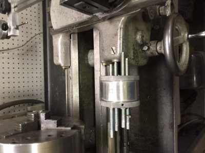
A 4 POSITION WAY STOP FOR THE SOUTH BEND 9 INCH LATHE
I have for sometime wanted a multi position way stop for my South Bend lathe. It would make projects like graduated dials much easier to make. The problem is when they are available on the internet auction sites, they are always in the $150 to $200 range and to me that is a ridiculous price. So, I decided to make one similar to the original South Bend design.
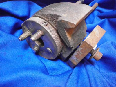
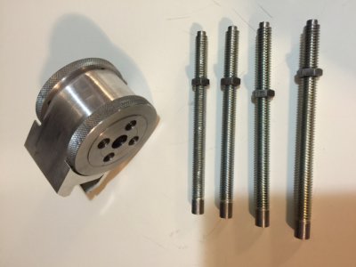
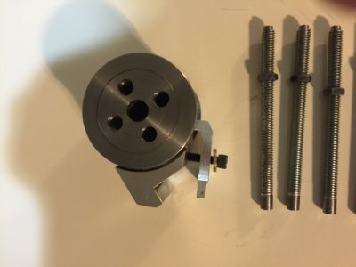
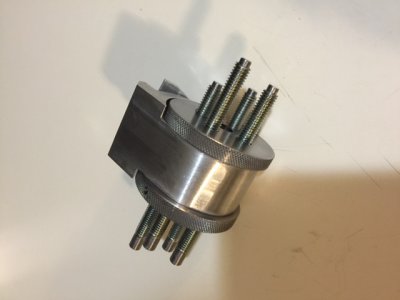
The above photo is the design I chose. It has 4 stops that rotate to position. I set out to draw a pattern and from that, I made my print.
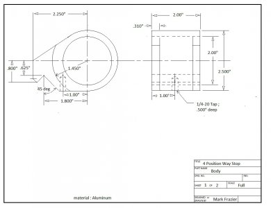
The following print is for the body of the way stop. I made it from aluminum because it is easy to work with and is plenty sturdy enough for this project.
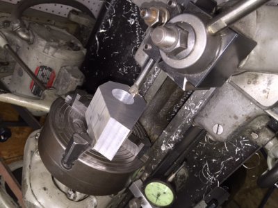
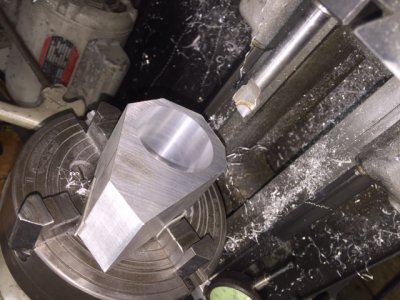
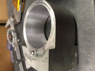
The above photos show the aluminum body that has been rough cut to shape on the band saw, put in the 4 jaw chuck and being bored to a 2.000” diameter hole.
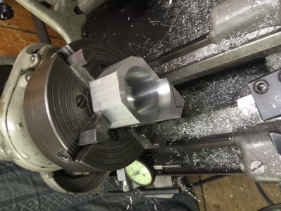
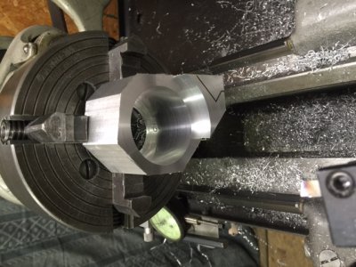
The above photos show the recess faced to a depth of .310” , then the part is flipped around and the second side is also faced to a depth of .310”.
The part is then moved to the mill to finish shaping and remove the corners to get the body closer to a round shape.
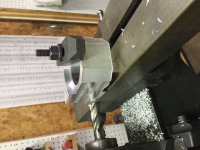
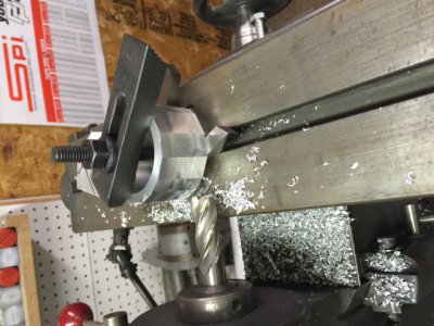
By rotating the part and milling the corners, the part becomes closer to being round. I could have mounted the part on the rotary table and milled the part to a round shape , but I wanted to illustrate another method of getting the same results for those who do not have the luxury of a rotary table. After the corners are milled off a couple of times , the part is dressed on the belt sander to finish.
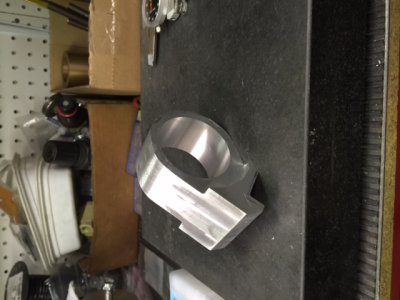
The above photo shows the finished body for the 4 position way stop. Notice the notch for mounting on the ways is milled. This was done by clamping the part in a vise on the mill with the flat bottom at a 45 degree angle and milling a slot to the specified depths. A ¼-20 tapped hole was also drilled and tapped in the bottom as specified in the print. Except for painting, this body is completed.
The next part to make is the tumbler that holds the four adjustable stops. The following print details this part which is made from a solid piece of cold finish steel bar stock.
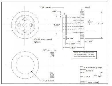
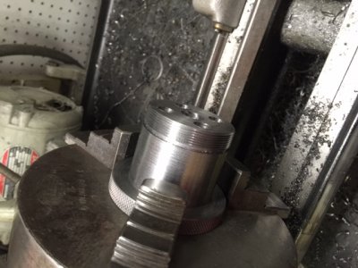
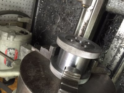
I started with a piece of 3” diameter steel round stock about 4 inches long. The first step was to turn the diameter to 2.750”. This is the diameter of the knobs on the tumbler. The next step was to knurl 1 inch of the length of the steel. The part was then turned around in the chuck and turned to a diameter of 1.999” for a sliding fit into the aluminum body. The following photo shows the knurled part being turned to the 1.999” diameter
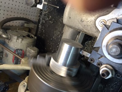
The 1.999” diameter is 1.755” long.
After turning this diameter, a .500” hole is drilled through the center and a groove was machined on the O.D. with a parting tool to a depth of .040” where the threads will stop. I also took the time to lay out a circle at a 1.250 diameter and two lines intersecting at 90 degrees on the end of the part. This was easy to do by scribing with the cutting tool and gives the locations of the four holes for the stops. After all this is done, the part is taken to the band saw and half of the 1.00” knurled end is sawn off to make the other end of the tumbler.
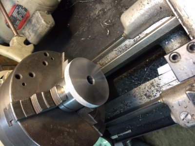
The tumbler is then placed back in the lathe and the end of the piece is faced off so the knob is .375” thick. If you look closely at the photo, you can see the groove where the threads will stop on the other end. This part is removed from the lathe and the end that was sawn off is mounted in the chuck and bored in the center to a diameter of 1.935”. This is the minor diameter of the threads that will be machined here.
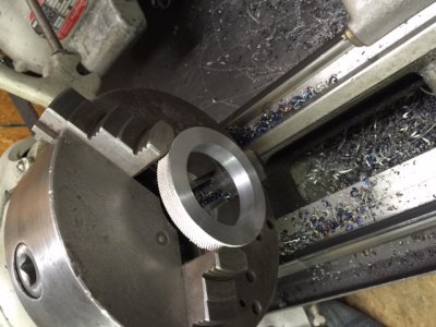
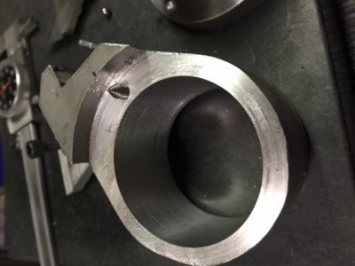
This part was faced and bored to 1.935" and will be threaded before removing from the chuck. This is done to insure the face and threads are kept square with one another to get a good fit when the tumbler is assembled in the body. The outer face will be machined later.
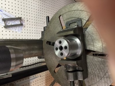
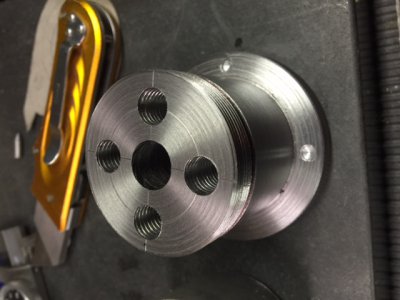
Using the marks laid out previously, four .3125” holes were drilled through the length of the tumbler. Then the holes are enlarged to .375” to a depth of 1.125”. it is important to make sure this is done on the end that is going to be threaded. After drilling the holes are tapped through at 3/8-16 threads.
Keep watching for the finish of this piece of tooling.
I have for sometime wanted a multi position way stop for my South Bend lathe. It would make projects like graduated dials much easier to make. The problem is when they are available on the internet auction sites, they are always in the $150 to $200 range and to me that is a ridiculous price. So, I decided to make one similar to the original South Bend design.

The above photo is the design I chose. It has 4 stops that rotate to position. I set out to draw a pattern and from that, I made my print.
The following print is for the body of the way stop. I made it from aluminum because it is easy to work with and is plenty sturdy enough for this project.


The above photos show the aluminum body that has been rough cut to shape on the band saw, put in the 4 jaw chuck and being bored to a 2.000” diameter hole.


The above photos show the recess faced to a depth of .310” , then the part is flipped around and the second side is also faced to a depth of .310”.
The part is then moved to the mill to finish shaping and remove the corners to get the body closer to a round shape.


By rotating the part and milling the corners, the part becomes closer to being round. I could have mounted the part on the rotary table and milled the part to a round shape , but I wanted to illustrate another method of getting the same results for those who do not have the luxury of a rotary table. After the corners are milled off a couple of times , the part is dressed on the belt sander to finish.

The above photo shows the finished body for the 4 position way stop. Notice the notch for mounting on the ways is milled. This was done by clamping the part in a vise on the mill with the flat bottom at a 45 degree angle and milling a slot to the specified depths. A ¼-20 tapped hole was also drilled and tapped in the bottom as specified in the print. Except for painting, this body is completed.
The next part to make is the tumbler that holds the four adjustable stops. The following print details this part which is made from a solid piece of cold finish steel bar stock.

I started with a piece of 3” diameter steel round stock about 4 inches long. The first step was to turn the diameter to 2.750”. This is the diameter of the knobs on the tumbler. The next step was to knurl 1 inch of the length of the steel. The part was then turned around in the chuck and turned to a diameter of 1.999” for a sliding fit into the aluminum body. The following photo shows the knurled part being turned to the 1.999” diameter

The 1.999” diameter is 1.755” long.
After turning this diameter, a .500” hole is drilled through the center and a groove was machined on the O.D. with a parting tool to a depth of .040” where the threads will stop. I also took the time to lay out a circle at a 1.250 diameter and two lines intersecting at 90 degrees on the end of the part. This was easy to do by scribing with the cutting tool and gives the locations of the four holes for the stops. After all this is done, the part is taken to the band saw and half of the 1.00” knurled end is sawn off to make the other end of the tumbler.

The tumbler is then placed back in the lathe and the end of the piece is faced off so the knob is .375” thick. If you look closely at the photo, you can see the groove where the threads will stop on the other end. This part is removed from the lathe and the end that was sawn off is mounted in the chuck and bored in the center to a diameter of 1.935”. This is the minor diameter of the threads that will be machined here.

This part was faced and bored to 1.935" and will be threaded before removing from the chuck. This is done to insure the face and threads are kept square with one another to get a good fit when the tumbler is assembled in the body. The outer face will be machined later.

Using the marks laid out previously, four .3125” holes were drilled through the length of the tumbler. Then the holes are enlarged to .375” to a depth of 1.125”. it is important to make sure this is done on the end that is going to be threaded. After drilling the holes are tapped through at 3/8-16 threads.
Keep watching for the finish of this piece of tooling.


