- Joined
- Jan 1, 2014
- Messages
- 233
[h=2]A DRO system for my King PDM 30 (RF 31 style) round column bench mill[/h]
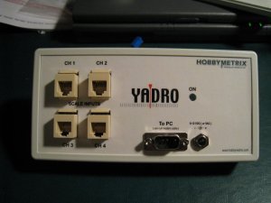
As most reader will know, counting hand wheel turns is a necessary evil when moving around a work piece to make sure you are in the right .100" bracket. Accurate and visible layout can also help in ensuring the drill or end mill is in the right place, but if you have ever had to go back and start counting turns over again, it doesn't take long to wish for a better system. A DRO is the only solution I know of. I had already installed a 6" digital caliper on the Z but wanted a 3 axis "system". I looked at Shooting Star, Schumatech and others but money or wait times kept me looking. I found a company called "Hobbymetrix" on line. The all in cost for 6", 8", 20" scales, their YADRO (YetAnotherDRO) interface, and connecting cables worked for me so I took the plunge. At the time they had some serious electronic supplier issues which resulted in me getting one of their "lab" boards, so that saved me all the angst of soldering in all of the components, I just had to finish out the case and the plug in wires. The YADRO actually has a 4 axis capability if you have a knee mill. There is a pile of detailed information on this product at "Hobbymetrix.com".
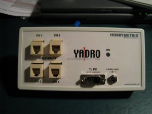
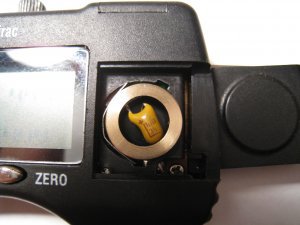
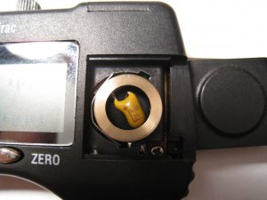
The finished YADRO interface box is 1-1/2"x3-1/2"x7". A small capacitor needs to replace the battery in each scale as they now get their power through the interface (as I understand it, a capacitor helps to smooth out any voltage variations). I made a simple brass ring the size of a battery with a plastic shell pressed in from the back which accommodates the capacitor, pinches the positive wire to the rim and feeds the negative wire out the bottom to make contact on installation as a normal battery would.
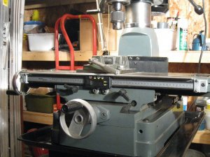
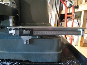
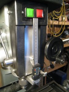
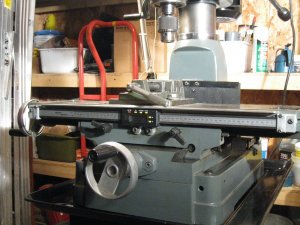
Several operating conditions dictated how I would mount the scales. The kind and amount of machining I do doesn't warrant the cost of a X servo, so displacing the possibility of travel stops on the front area of the table is not a biggy, and, a front mount doesn't cause me to loose any Y travel which a rear mount would. For the Y, the back face of the saddle was machined making it easy to make a bracket and have the Y scale stick out the back and also staying out of the way of the Y gib locks. The Z is mounted centre front after taking out everything associated with the old quill depth stop and putting in a flat AL plate. I made custom AL mounts for the ends of all the scales and and a new bottom quill bracket which accommodates the Z scale on the front, and my quill return cable attached to the rear. AL angle protects the X and Y scales. (just a note - the X and Y reader mounts in these pictures are first try rigid types, later replaced as shown below).
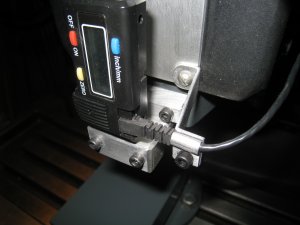
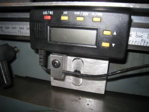
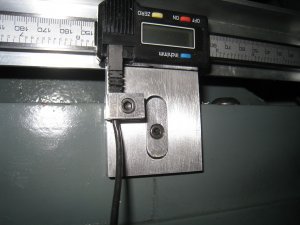
Anchoring the reader heads caused me some concern. The X scale had a slight bow in it (front to back) over its 26" length, and, while somewhat flexible, I didn't want to put any stress on the readers as they travel along. Similarly, on the Y and Z, it is difficult to ensure that the scales are perfectly true to the line of movement. Also, on the Y, the only place to attach the reader bracket was to the cast surface of the mill base. For all three axis I therefore used a "plate and insert" anchoring system. Each reader has a plate attached to it with a milled slot with an associated very close fitting plug. The plug (which I keep oiled) allows for motion on two axis to relieve any alignment stress as the reader moves along. Also, at each reader, cable clamps were installed to ensure cable plug-in continuity is maintained.
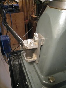
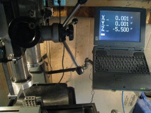
Finally, I needed somewhere to hang an old Toshiba laptop which is used for the display. This is part of the YADRO approach to keeping costs down and gives a nice big readout. The solution I used was to make a mount on the back of the column base and make up an articulated arm using pipe and pipe fittings. Not very elegant but it works a treat. The display can be moved around at will. A plywood platform supports the laptop and the interface is mounted on the underside to keep it out of the way.
Hobbymetrix was very helpful with explicit instructions. The system cranked up on the first try and has been very reliable ever since. There is no noticeable "lag" to the readout and the system has all the capabilities that I need.
Critique and suggestions always welcome.


The finished YADRO interface box is 1-1/2"x3-1/2"x7". A small capacitor needs to replace the battery in each scale as they now get their power through the interface (as I understand it, a capacitor helps to smooth out any voltage variations). I made a simple brass ring the size of a battery with a plastic shell pressed in from the back which accommodates the capacitor, pinches the positive wire to the rim and feeds the negative wire out the bottom to make contact on installation as a normal battery would.


Several operating conditions dictated how I would mount the scales. The kind and amount of machining I do doesn't warrant the cost of a X servo, so displacing the possibility of travel stops on the front area of the table is not a biggy, and, a front mount doesn't cause me to loose any Y travel which a rear mount would. For the Y, the back face of the saddle was machined making it easy to make a bracket and have the Y scale stick out the back and also staying out of the way of the Y gib locks. The Z is mounted centre front after taking out everything associated with the old quill depth stop and putting in a flat AL plate. I made custom AL mounts for the ends of all the scales and and a new bottom quill bracket which accommodates the Z scale on the front, and my quill return cable attached to the rear. AL angle protects the X and Y scales. (just a note - the X and Y reader mounts in these pictures are first try rigid types, later replaced as shown below).


Anchoring the reader heads caused me some concern. The X scale had a slight bow in it (front to back) over its 26" length, and, while somewhat flexible, I didn't want to put any stress on the readers as they travel along. Similarly, on the Y and Z, it is difficult to ensure that the scales are perfectly true to the line of movement. Also, on the Y, the only place to attach the reader bracket was to the cast surface of the mill base. For all three axis I therefore used a "plate and insert" anchoring system. Each reader has a plate attached to it with a milled slot with an associated very close fitting plug. The plug (which I keep oiled) allows for motion on two axis to relieve any alignment stress as the reader moves along. Also, at each reader, cable clamps were installed to ensure cable plug-in continuity is maintained.


Finally, I needed somewhere to hang an old Toshiba laptop which is used for the display. This is part of the YADRO approach to keeping costs down and gives a nice big readout. The solution I used was to make a mount on the back of the column base and make up an articulated arm using pipe and pipe fittings. Not very elegant but it works a treat. The display can be moved around at will. A plywood platform supports the laptop and the interface is mounted on the underside to keep it out of the way.
Hobbymetrix was very helpful with explicit instructions. The system cranked up on the first try and has been very reliable ever since. There is no noticeable "lag" to the readout and the system has all the capabilities that I need.
Critique and suggestions always welcome.


