- Joined
- Jun 17, 2011
- Messages
- 2,063
A few of us ordered iGaging DROs recently. Mine arrived last week and I finished the installation this morning. Since I'm also building a taper attachment (future post), I needed to incorporate the two projects to make both work.
I did the carriage (Y-axis) first. I had already used the same DROs on my mill, so I had parts left over and got the first bit done the same day I ordered the DROs. The heavy plate at the back of the carriage is where the taper attachment will mount. It made sense to use it as the anchor point for both axes.
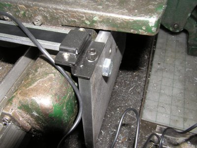
I made a bracket to mount the sensor to the saddle near the front. I find that the scales are sufficiently supported to use only one end mount. The sensor adds lots of support. The advantage, other than not having to make an arm to attach to the apron, is an extra couple of inches of readable length.
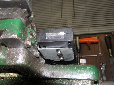
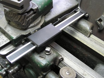
There is enough room on the right side of the carriage for the sensor. It doesn't interfere with either the carriage locking screw or the compound. The corner of the sensor is just far enough back to allow an Allen wrench into the compound locking setscrews. (I had replaced the external square-head screws to avoid chuck strikes.) If the scale ever gets in the way of a particular tailstock operation, I can remove it with just one screw.
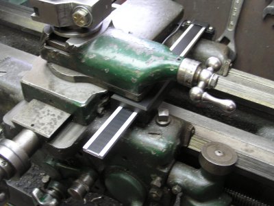
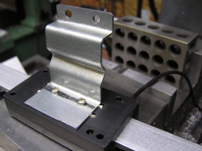
The X-axis scale required a new bracket as well. It turned out a bit longer than required, but rather than keep remaking it until it fit, I added the Z-bends in the middle. This made it slightly adjustable. The two holes at the top of the picture allow it to mount to the bottom edge of the rear plate.
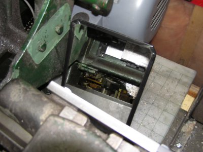
Drilling and threading the mounting holes at the back of the lathe bed was a bit of a challenge, since I don't have the room (or the desire) to move the lathe out to work from the back. I used my little Milwaukee M12 angle drill and a mirror to help aim. :biggrin:
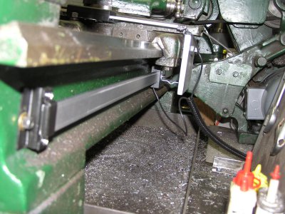
By moving the carriage down to each end before centre-punching the holes, I got them close enough to the right place to be able to adjust them later. Notice the split-loom covering the two cables to the display heads.
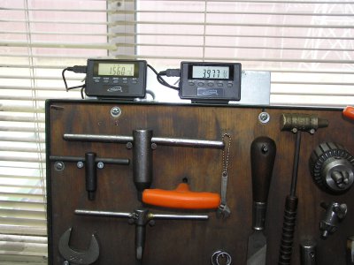
After all that, I just needed to add a steel plate at the top of my tool board to mount the displays. I adjusted the angle of the plate to minimize glare from the room lights. As on my mill, the right one is the X-axis and the left one is the Y.


I did the carriage (Y-axis) first. I had already used the same DROs on my mill, so I had parts left over and got the first bit done the same day I ordered the DROs. The heavy plate at the back of the carriage is where the taper attachment will mount. It made sense to use it as the anchor point for both axes.

I made a bracket to mount the sensor to the saddle near the front. I find that the scales are sufficiently supported to use only one end mount. The sensor adds lots of support. The advantage, other than not having to make an arm to attach to the apron, is an extra couple of inches of readable length.


There is enough room on the right side of the carriage for the sensor. It doesn't interfere with either the carriage locking screw or the compound. The corner of the sensor is just far enough back to allow an Allen wrench into the compound locking setscrews. (I had replaced the external square-head screws to avoid chuck strikes.) If the scale ever gets in the way of a particular tailstock operation, I can remove it with just one screw.

The X-axis scale required a new bracket as well. It turned out a bit longer than required, but rather than keep remaking it until it fit, I added the Z-bends in the middle. This made it slightly adjustable. The two holes at the top of the picture allow it to mount to the bottom edge of the rear plate.

Drilling and threading the mounting holes at the back of the lathe bed was a bit of a challenge, since I don't have the room (or the desire) to move the lathe out to work from the back. I used my little Milwaukee M12 angle drill and a mirror to help aim. :biggrin:

By moving the carriage down to each end before centre-punching the holes, I got them close enough to the right place to be able to adjust them later. Notice the split-loom covering the two cables to the display heads.

After all that, I just needed to add a steel plate at the top of my tool board to mount the displays. I adjusted the angle of the plate to minimize glare from the room lights. As on my mill, the right one is the X-axis and the left one is the Y.


