Breakout Board Wiring

jbolt

Active User
H-M Supporter Gold Member
Joined
Dec 3, 2013
Messages
1,844
I have this breakout board shown below. The step driver wiring is straight forward but I'm not sure how or if I can use this board to trigger a relay to start and stop the spindle and coolant pump?

5axis breakout.JPG

Manual attached

Thanks,

Jay

5axis breakout.JPG
 

Attachments

  • 5 Axis CNC Breakout Board.pdf
    786.4 KB · Views: 17
Jay,
Looks like the board only has one relay output. You could use it for either the spindle or coolant but would need another board for the second relay.

Dave
 
I used 5v electronic relays on my mill. 5v to trigger and 120v switching. I got them on ebay.
then you use any open output pin to trigger the relay.
steve
 
Use the BOB to switch the spindle on vis the VFD. Use the VFD to control the relay for the coolant. You will be able to set timings on the VFD's built in intelligent relay. Use that for example to keep the coolant running for awhile even though the spindle is stopped - that way if you start a second job saw within 90 seconds the coolant never shuts off. After 90 seconds then the coolant pump shuts off.
 
Thanks for the replies.

I think I finally wrapped my head around this. I'm a nuts and bolts guy so sometimes its difficult to visualize the electrical connections.

The relay on the breakout board is a pass-through switch with NO, COM and NC connections. So in my case I will be using DC to AC solid state relays (SSR) to toggle the device on/off. All that needs to be done is run one leg of the low volt circuit through the BOB relay NO & COM and set the the appropriate output pin in Mach3 (pin 14 for this board set to active high). When the BOB powers up the relay will be open (NO) so nothing will start. When the input in Mach3 is toggled it goes "high" closing the BOB relay and completing the circuit to the SSR.

The "B" axis is not being used for a motor so the Step (pin 16) and Dir (pin 17) are available as outputs. Again using an SSR, the DC (-) side of the relay is wired to GND and the (+) side of the relay goes to pin 16 or 17. When activated (high) by Mach3 the pin applies 5v and activates the SSR.

I confirmed the wiring with a multi-meter and then tested each with a SSR wired to a flood light. Works!!!

My mill finally be delivered tomorrow (YAY!!!) so I will be able to see how the spindle motor is switched so I may have more questions about integrating that.

bloomingtonmike - thanks for the help. Currently the mill is just on/off, no VFD. That may come later.

jumps4 - A buddy gave me a dozen SSR-25DAs with heat sinks. I think these should work okay.


Jay
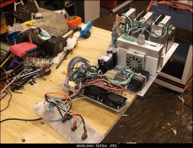
 
I wired my controller box mostly low voltage and have a plug and cable to run to the machine base. I'm putting the motor and coolant electronic relays in there. another incompleted project of mine. right now the control panel is being used and I'm switching on my spindle and coolant manually. everything is wired I just never hooked it to the mill and pump.
the same bob is in this mess lol
steve

DSCF0220.JPG
 
Last edited:
Steve,

How is the motor switch configured on your mill? Does it have a motor contactor? Since my mill came with a power table feed and a powered z-axis my control box is full of motor contactors and switches . When I do the conversion I will be removing the two power feed motors and associated wiring. I need to wrap my head around the wiring for the spindle motor using SSR's.
Jay

I wired my controller box mostly low voltage and have a plug and cable to run to the machine base. I'm putting the motor and coolant electronic relays in there. another incompleted project of mine. right now the control panel is being used and I'm switching on my spindle and coolant manually. everything is wired I just never hooked it to the mill and pump.
the same bob is in this mess lol
steve
 
my mill is different and I still switch it on manually. I wired the controller box but not the mill.
If you send me a copy of your mill wiring diagram i'll give it a look.
steve
 
Back
Top