Carriage play at back of ways ??...

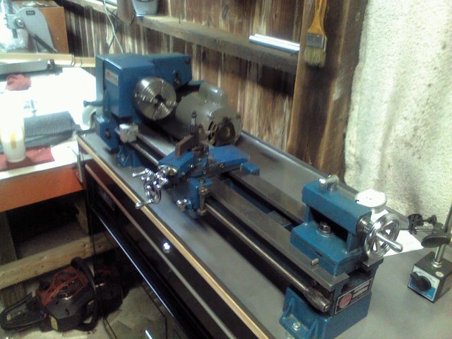
You are not going to be able to align the bed on a flimsy rolling cabinet with only a piece of plywood on top, the bed is stronger than what you have attached it to. The forces acting on the cut are not all downwards, but also towards the front of the machine, which could lift the back of the carriage. I do not see how a cut that is constant throughout the length of the cut could create a taper situation. Do an experiment and add weight to the back of the carriage to hold it down, perhaps 10 - 20 lbs weight and see if it makes a difference.

I have it mounted through 3/4 inch solid wood top sandwiched between the 11 ga, chip pan & 11 ga. metal the cabinet is constructed of. Is that not sufficient ?? I'll try to find a way to attach a 20 lb. plate to the back of the carriage, though there isn't a lot to work with back there, and see if it helps.

Z7tXju9l.jpg
 
The Z axis is from the TS to the HS on a lathe. I think you mean in the Y axis direction if that was possible or straight up? Do you have an anti-lift device (gib) on either or both ways on the bottom of the carriage? They will run under the bed ways. If so adjust the movement out.

Yes, straight up... I just have the bearing plates that ride along the underside of the ways. After moving the carriage to the end of the bed as Robert suggested, the measured movement decreased to 0.001, so I may just have to live with some bed wear.
 
Here's the the way I have it set up right now with the 1"x 5.75" round bar in the 4-jaw...

QV98CCQl.jpg


The line closest to the chuck jaws marks the 5" point on the bar. The taper at the chuck end of the cut is smallest at 0.990 and grows to 0.993 at the right end of the bar. The cut in the above pic was just to remove material to provide the 2 collars that I planned on using to make the test cuts...will the 2 collar method work to solve the taper issue ?? It kept popping up repeatedly when I was searching on lathe leveling so I believed it to be correct for correcting the unwanted taper. I ran the carriage to the end of the bed as you advised & measured again to find the "lift" had decreased to 0.001, so maybe I'm looking at some bed wear closer to the headstock ??

This was the part I was making when the unwanted taper turned up...

CHbplN1l.jpg


The center was already bored to 1.750" & the starting diameter of the piece was originally 3". I only took light cuts (0.005) as to not push the machine too much and had no idea as to the type/grade of steel, also had not worked with a piece this large until now. Took some time but I got it down to 2.267 as measured at the collar & 2.270 at the bottom end. I'll look into a pipe center for next time. Thanks.

If I set the magnetic base of the DI on the carriage chip shield and set the indicator plunger up along side of the cutting tool to "see" the work as the cutter does, will the DI indicate the taper as I move the carriage toward the headstock ?? What I'm asking is will the DI needle move 0.003 as I move it along the length of the cut in the same path the cutting tool followed ??
 
Every lathe has a certain amount of spring, I'm not sure if that's what you're dealing with but a bullnose live center might help that setup.

I've had good luck ordering stuff for my Mark II from these guys.


John
 
To answer your last question first, no. The DI probably won't move any at all because it will be following the same path that it followed in producing the slight taper. But if your lathe were perfectly straight and the slightly tapered part had been made on another machine that was not straight, the DI would move 1.5 thou, not 3.0. But not knowing the source of the error, if you were to mount a perfectly ground test bar in the 3-jaw chuck and run the DI along it, the DI could move anywhere between zero and 3.0 thou. Depending upon where the error is.

The error most likely has nothing to do with the carriage lifting. It could be caused by the spindle not being parallel to the ways, as I said earlier. It could also be due to runout or angular wobble in the chuck. Or both.

If you can acquire one, mount a ground test bar in the chuck and run the dial indicator against it. Return the carriage to the right end of the test bar and rotate the chuck and spindle and measure the wobble if any. Between the two methods, you should be able to determine which of the two possible culprits is the cause or that both are contributing to it. You might, if the error is primarilly in the chuck, be able to rotate the work piece 180 degrees in the the chuck and salvage the part.
 
Thanks to all who helped with getting the lathe set up. I have it dialed in to 0.0005 over the 5" length of the bar, which is the lowest resolution the 0-1" micrometer I have goes.
 
Thanks to all who helped with getting the lathe set up. I have it dialed in to 0.0005 over the 5" length of the bar, which is the lowest resolution the 0-1" micrometer I have goes.
glad you fixed the issue, though 3" diameter work on that size lathe is probably near the limit
 
Back
Top