A thread to share a few pics & experiences with my new machine. It's an Optimum TU3008G lathe, 300mm swing, 700mm between centres (12x28") I also have the BV20 milling attachment bolted on the back. These were bought new from Machinery House in NZ. Being a mostly European & Antipodean brand there isn't quite as much online info around on these machines compared with ones that are common in North America.

The lathe was just the right size to fit in where my old Atlas 10F used to sit but is a pretty massive upgrade in terms of precision machining capability.
The first job before installing the new machine was to reinforce dad's old bench. A big chunk of channel was swapped for beers at a local structural steel workshop then grafted into place.

I discovered that the supplied chip pan is lower at the edges than under the lathe base - designed to go on the optional stand obviously but a problem for putting it flat on a bench. So some 25mm packers were needed, I had nothing that thick in stock but it was an easy job for the local CNC profile cutters. I work in the pulp & paper industry & there are lots of useful engineering supplies & services available close to the mills I visit in nearby Kawerau.

By this stage I had already removed the chuck guard & cutout. I'm not usually so quickly dimissive of safety features but it looked like it would seriously get in the way when using the 4 jaw chuck & the manual recommended lifting from the spindle as seen above which would have definitely bent the chuck guard if left in place.
Then it was on to levelling 'er up with shims & mounting the mill on straight... Thanks to the guys at one of the mills for the loan of the precision level!


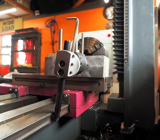
At which point I discovered an issue I still need to deal with. The cross slide is tilted down towards the chuck by about 0.13mm over it's width. Not great on a brand new machine.

This is mostly in the saddle ways but also a little in the cross slide. (Pic above shows using the new chuck jaws as paralells) I'll probably get the cross slide top ground to correct for the slope. Machinery house have offered another better saddle but I'm suspicious of how well that would mate with the main bed ways. It was good to strip the saddle anyway as the factory lube under there appeared to be a mix of waste oil & grinding dust. Otherwise it has checked out ok, some minor fettling required here & there but there are a few things I still need to verify like the 2 collar test etc.
It was never worth investing too much in accessories for the old Atlas & I'm starting from zero for milling equipment so the tooling spend has been substantial & ongoing... I did budget for it a bit though. This lathe didn't come with many included extras like steadies, 4 jaw chuck etc, that all had to be bought separately.

Next on the list was modifying the rear splash guard to fit around the mill & adding space for a shelf.

Also made it two piece so it's easily removable, the machine is jammed up against a wall for maximum space efficiency.
My first milling project was a metric drawbar for the mill spindle. Bizarrely for an Asian made, Euro market machine, the drawbar is 1/2" Whitworth. It came with a drill chuck arbor to suit so I got a chuck for that. With the tooling I bought with the machine I got a face mill & asked for an arbor to suit the machine - this was a mistake, should have just gone all metric from the start as now I have to swap the drawbar around for my other MT3 tooling that is all M12x1.75 until I buy another couple of arbors & swap them over.

Second project was to machine down the lathe chuck key which was too big. The supplied 3 jaw chuck seems like a decent piece but the precision didn't extend to the chuck key unfortunately. At least it needed to be 3/8" so I could use a socket set in the meantime. An insert end mill zipped through the hardened key no problem. I got some Aliexpress MT3 collets to use in the mill spindle as that seemed like a good way to keep things rigid & gain some Z travel. One nice thing about this setup is that the mill & the tailstock are MT3 & it came with an MT3 adapter for the MT5 lathe spindle, so the same tooling can slot in anywhere.

Cheers
Clint
The lathe was just the right size to fit in where my old Atlas 10F used to sit but is a pretty massive upgrade in terms of precision machining capability.
The first job before installing the new machine was to reinforce dad's old bench. A big chunk of channel was swapped for beers at a local structural steel workshop then grafted into place.
I discovered that the supplied chip pan is lower at the edges than under the lathe base - designed to go on the optional stand obviously but a problem for putting it flat on a bench. So some 25mm packers were needed, I had nothing that thick in stock but it was an easy job for the local CNC profile cutters. I work in the pulp & paper industry & there are lots of useful engineering supplies & services available close to the mills I visit in nearby Kawerau.
By this stage I had already removed the chuck guard & cutout. I'm not usually so quickly dimissive of safety features but it looked like it would seriously get in the way when using the 4 jaw chuck & the manual recommended lifting from the spindle as seen above which would have definitely bent the chuck guard if left in place.
Then it was on to levelling 'er up with shims & mounting the mill on straight... Thanks to the guys at one of the mills for the loan of the precision level!
At which point I discovered an issue I still need to deal with. The cross slide is tilted down towards the chuck by about 0.13mm over it's width. Not great on a brand new machine.
This is mostly in the saddle ways but also a little in the cross slide. (Pic above shows using the new chuck jaws as paralells) I'll probably get the cross slide top ground to correct for the slope. Machinery house have offered another better saddle but I'm suspicious of how well that would mate with the main bed ways. It was good to strip the saddle anyway as the factory lube under there appeared to be a mix of waste oil & grinding dust. Otherwise it has checked out ok, some minor fettling required here & there but there are a few things I still need to verify like the 2 collar test etc.
It was never worth investing too much in accessories for the old Atlas & I'm starting from zero for milling equipment so the tooling spend has been substantial & ongoing... I did budget for it a bit though. This lathe didn't come with many included extras like steadies, 4 jaw chuck etc, that all had to be bought separately.
Next on the list was modifying the rear splash guard to fit around the mill & adding space for a shelf.
Also made it two piece so it's easily removable, the machine is jammed up against a wall for maximum space efficiency.
My first milling project was a metric drawbar for the mill spindle. Bizarrely for an Asian made, Euro market machine, the drawbar is 1/2" Whitworth. It came with a drill chuck arbor to suit so I got a chuck for that. With the tooling I bought with the machine I got a face mill & asked for an arbor to suit the machine - this was a mistake, should have just gone all metric from the start as now I have to swap the drawbar around for my other MT3 tooling that is all M12x1.75 until I buy another couple of arbors & swap them over.
Second project was to machine down the lathe chuck key which was too big. The supplied 3 jaw chuck seems like a decent piece but the precision didn't extend to the chuck key unfortunately. At least it needed to be 3/8" so I could use a socket set in the meantime. An insert end mill zipped through the hardened key no problem. I got some Aliexpress MT3 collets to use in the mill spindle as that seemed like a good way to keep things rigid & gain some Z travel. One nice thing about this setup is that the mill & the tailstock are MT3 & it came with an MT3 adapter for the MT5 lathe spindle, so the same tooling can slot in anywhere.
Cheers
Clint
Last edited: