Converting reversing 110V motor to 220V

raferguson

Registered
Registered
Joined
Jul 22, 2019
Messages
29
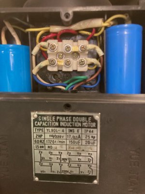
I have been tripping breakers occasionally on my mill-drill, so I got around to installing a 220V outlet. The plaque on the motor said 110//220V, and had a wiring diagram. However, when I took off the cover, the wiring diagram looked nothing like what I saw. I know a little bit about electric motors, and guess that the field gets reversed relative to the armature to reverse the motor, but I do not know where to start rewiring in this case. Is it possible that by reversing the motor they made it impossible to rewire for 220V? I could buzz out the wires, but not sure that would help me. The power goes to the reversing switch, and two cables (field and armature?) go from the reversing switch to the motor. It looks like the wiring comes in the bottom of the box, and then there are wires that go from the box to the motor at the top.

I could in theory install a 110V 30 amp circuit instead and bypass the problem, but I would have to run new wires, plus buy a new breaker, spool of 10ga wire, and a new outlet, so that would be quite a bit of work and expense. With less effort, I could make it a dedicated 110V 20 amp circuit, but not sure that would solve the tripping problem, as the other things on the previous circuit draw little power. My cheap clamp on ammeter says the circuit pulls 2 amps idling, presumably control circuits on stoves and garage door openers. The dedicated 110V circuit would make my wife happy, because I would not screw up the gas stove clock when the breaker trips.

Thanks in advance for your thoughts.

Richard

Mill wiring.jpg
 
Last edited:
A single phase induction motor does not have a wound rotor, mu guess is that the links between terminals need to be moved for 220V operation.
 
Easy peasy. Give me a few mins...
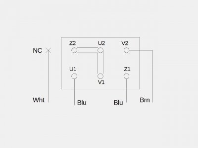
Reconfigure the terminal straps as shown, and disconnect the white wire and tape it up.
Provide 240 volts to the power cord and you should be good to go
If the motor turns reverse of desired, disconnect the blue from Z1 and install the white instead (tape the blue)
Be sure the machine has a good ground
240motconv120a.jpeg
 
Last edited:
Mark:

Can you explain how you figured that out? What do the various terminals do? Does the fact that it is a reversing motor make a difference? Do the names of the various terminals mean anything?

It looks like you are looking at the lower left of the wiring diagram. Why is there a lower right of the wiring diagram? Or for that matter, why is there an upper right of the wiring diagram? It is just confusing. That is part of what makes me nervous, that I do not know which terminal does what, and there are a lot of wires.

Thanks.

Richard


Easy peasy. Give me a few mins...
Reconfigure the terminal straps as shown, and disconnect the white wire and tape it up.
Provide 240 volts to the power cord and you should be good to go
If the motor turns reverse of desired, disconnect the blue from Z1 and install the white instead (tape the blue)
Be sure the machine has a good ground
 
The motor is showing you the configurations for the two rotational directions; clockwise and counterclockwise, but it doesn't show the reversing switch details. That's why there are 4 wires coming in instead of just two power wires. Two wires are main power and the other two are power for the start circuit (start leg). 240volt reversing operation only requires 3 wires instead of 4 for 120volt; in both cases the start leg only "sees" 120 volts.
I figured this stuff out years ago- been into electronics a long time. I seem to be the resident motor and switch expert here LOL
The U, V, and Z nomenclature is pretty much standardized-at least for import motors. U and V are main power windings and Z is for the start circuit.

The motor reverses by swapping the phase relation between those two.
I think you will find the motor is "snappier" and cooler running on the higher voltage- your switch will last longer too since the current is half what it was on 120 volt. Enjoy.
 
Last edited:
This mil/drill has a reversing switch, correct?
 
Reconfigure the straps as Mark has shown, but you will not need to disconnect the white wire. If you look at the 220 volt connection diagrams, you'll see that Z2 is always connected to U2 and V1, which is the center point of the series connection of the "run" windings. What causes reversing is Z1 being moved from V2 to U1. Z1 and Z2 are the "start" windings, as Mark stated.
 
Marc:

Thanks very much. I did exactly what you said, and it worked. I held my breath for a moment before I flipped the switch. It even ran in the right direction.

After I did that, I saw jbobb's post. I did not try to leave the white wire on, although the wiring diagram implied that I did not need to remove the white wire, to my reading.

I duly taped up the white wire, and checked the ground with a continuity tester. Should I try to measure the resistance to ground?. I also checked that the outlet had a good ground, with my voltmeter.

Gracias,
Richard
 
Last edited:
I have to respectfully disagree- the white wire must be disconnected from Z2-(either at that end or at the switch)-bad things would happen otherwise
Sounds like you are good to go Richard
 
Last edited:
Back
Top