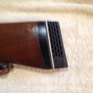
I have seen this answered before, but now that I need it I can't find it. I need a program to calculate stair steps for cutting a large convex on a mill. The stock is 3/8" X 1-1/2" X 5" 6061. It is a butt plate adapter for a Savage 99. My boys eyes aren't all that great and he wants to try out my father in-law's gun. The stock is too short for him, so we are thinking about adding a recoil pad. I want to make an adapter to fit the gun so as to fit a flat recoil pad without cutting the stock. It's an older gun in excellent condition and I want to put it back in OEM condition.
I played around with the math stuff and came up with a 9.4098 R over 4". Ran it though CAD and cut out a 100% piece and it is pretty darn close. The only way I can do this is to do a set of measurements in CAD every 15-20 thousands and use the DRO. Will the DRO directly calculate all the steps for me? Can somebody send a link to a calculator that will do all this for me? I want get close enough to hand file to fit the gun stock.
Thanks in advance!!!! Charles