Custom Bench PSU

GreatOldOne

R'lyeh Engineering Works
H-M Supporter Gold Member
Joined
Mar 20, 2014
Messages
418
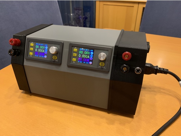
I've spent the last week designing and printing an enclosure for a bench PSU I've put together. I reckon it's come out pretty well. Takes a bloody long time to print though. The centre section alone is a 28 hour print... :D

289371

289375
289366
289374
289368
289367


If anyone is interested, the STLs are on thingiverse, here:
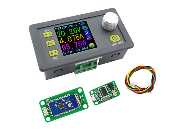
IMG_4080.jpg


IMG_7189.jpg


IMG_8091.jpg
 
Very stylish! You may need to add some cooling holes on the back- depending on the internal temperature
Mark
 
Last edited:
Id like more info on the inside parts of you would be willing to share please. More specifically how you wired the 2 CPUs together?
 
Very stylish! You may need to add some cooling holes on the back- depending on the internal temperature
Mark

No need. There is cooling slots on either end cap, and the PSU has a fan built in to draw air in one end and expel it out the other.

Id like more info on the inside parts of you would be willing to share please. More specifically how you wired the 2 CPUs together?

It’s all quite straight forward. The PSU has 3 positive and 3 negative screw terminals, supplying 48ish volts. Each of the controls (cpus as you call them) are wired to a pair of these on their input terminals, and then their output terminals are wired to a set of the red / black terminal posts on the case, with the positive side being routed through the fuse holders on the right most end cap.

These modules are more uptodate than mine, as they come with a comms board which allows you to talk to them via an app, but mine has the headers for the serial link, so I may mod them later to allow this.


I’m also toying with flashing the firmware on them to this, so I get a large print display - easier to read with my poor eyesight!
 
Back
Top