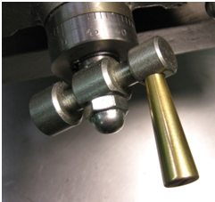
Drill press to mill conversions

master53yoda

Active User
Registered
Joined
Jan 15, 2013
Messages
171
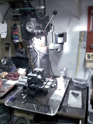
I have converted several drill presses to functional drill mills over the years, I am part way through the conversion of one I started this fall and I thought i would share the process here. I have had trouble getting pictures to post but i think i do have it resolved I have posted in an album some pictures that go with this project. Below is a general posting that i put up in another thread.

I have successfully converted multiple drill presses to mills. There are a few things that MUST be addressed.


  • [*=left]Replace the lower spindle bearing with a angular contact double row bearing of the 520x series is what I use. This resolves the side thrust issue on the bearing.

    [*=left]I go to a ER25 or 30 series collet systems with the proper Morse taper and either use a draw bar or a lockpin to retain the taper.

    [*=left]I have found that the table on the drill press isn't ridged enough for mill work, this won't be an issue if the table is rigidly mounted on ways. Most drill presses mount the table on the column and the end result isn't rigid enough. I cut the total height down, remount the head using a gib to make the head more rigid on the column I also gib the spindle to remove the excess slack in the spindle. I then mount the x y table directly to the base. If i can't find an older American cast 6x 12 or 18 x-y table I upgrade the bearings and tighten the scroll nut to remove as much backlash as possible from the lead screws.

    [*=left]some method of locking the spindle, I use the center point setscrew on the added gib if there is room for it.

    [*=left]The items below are nice but not absolutely necessary

    [*=left]A fine feed on the Z access is pretty hard to do without, I cast mine out of aluminum and use brass bearings for thrust adjustment for the fine feed, It is also designed to put aadd stepper motor for CNC if desired. I also go to external springs on the spindle to remove the play between the spindle and the z axis drive as the return spring on a drill press leaves down backlash on the spindle.

    [*=left]I go to a high end 1.75 to 3 hp treadmill motor (the ones that are rated at 4000 rpm or less) these will deliver a sold 3/4 to 1.5 hp in the operating range that they will be used on the mill. I normally limit the spindle speed to nothing higher then 3500 rpm and use a 3 or 4 step reduction pulley set. They will power tap and handle 3" face mill.

    [*=left]I normally will also set them up with a DRO

    [*=left]I use a z axes drive ( the angle motor off of a treadmill) to raise and lower the head on the column and also use a 1/2 or 5/8 auxiliary shaft to retain alignment on the column.


drill to mill modification.jpg


[FONT=&amp]
[/FONT]

drill to mill modification.jpg
 
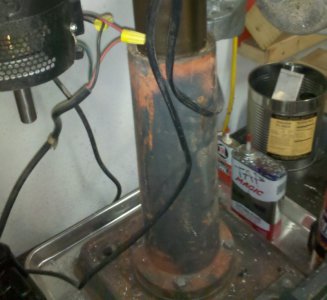
The first thing that I look at when contemplating a conversion is the Drill press that I am starting with. I look for a floor model that has a tall column attachment block to help the ridgidity issue. then I also look for one that has a broken table or possible damage to the upper column. This last project press was a craigslist find that had a broken table and bent rack. Neither of these where items that i would use in the end but it did allow me to get a solid 17" machine for $75.00 to start my project with. This drill press new is in the 500 to 950.00 range. As has been brought up many times if you were to pay new price for all the items for a conversion you would have 80% of a factory mill drill.

The other item that I look for but don't always find is the heavy quil lower bearing. These will allow the installation of the 5200 series angular contact bearing without modification. In this mill it had a 6203 series bearing which I was able to replace with a 5203 double row bearing without modification with the exception of the lock pin on the top of the upper bearing due to the quill being 3/16" lower then before. Even with the deep bearing block the bearing still hangs out about 3/16" below the bearing block, much more then that and I would have bored the bearing deeper in the block. These bearings new are about 40 to $50 but by watching Ebay I have been able to get new Fafnir bearings for under 15.00.

The double row angular contact bearings are the style bearings that the automotive industry has gone to for modular wheel bearings. This site has a quick description of angular contact bearings. http://www.astbearings.com/double-row-angular-contact.html

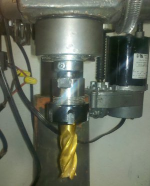
The collet is a MT2 to ER25 collet with a 5/8ths endmill.

Attached are pictures that go with this portion of the thread. I will be posting further descriptions as time goes on. Tonight I'm tearing down a couple transmissions that I will melt into ingots tomorrow to fill some cast aluminum ingot orders. I will share my casting furnaces in another thread as time and interest goes on.

d-m mill column .jpg d-m quill bearing.jpg
 
Last edited:
Dealing with the tapered chuck holding Issue


  • [*=left][FONT=&amp]I go to a ER25 or 30 series collet systems with the proper Morse taper and either use a draw bar or a lock-pin to retain the taper.[/FONT]
On this conversion I have gone to the ER25 series collets. I bought the HF set of end-mills and only need 3 collets for all that is there 3/8, ½, 5/8 . This gives me 3/16 to 5/8 mills I also will get a ¾ “ MT2 end-mill holder for ¾ shaft items and that I can modify for my 3’ face mill that I use, and for the boring head when I build it.

My son has a full machine shop up to a 30hp Hass CNC mill and if I really need something else I go and use his shop. He is production oriented and I’m more of “enjoy the feel , and the journey type. We give each other a bad time about our different views of the world.

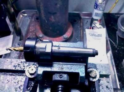
The spindle shaft was small enough that I did not want to bore it for the draw bar. So, on this conversion I’m using a lock-screw retainer. I drill and tap a 10-32 hole in the bottom collar of the spindle shaft. I then seat the MT2 collet and center drill about a 1/8”’ deep hole in the Morse taper. I then use a 60[SUP]o [/SUP]chamfer on the hole.

When I put the MT into the spindle I line up the Mt chamfer with the screw and push it in loosely, I then tighten down screw and it centers the taper on the chamfer, I then tap the taper home and finish tightening the setscrew, because the setscrew and the chamfer share the same center on a fully seated MT, by seating the MT and tightening the set screw the MT is locked in the fully seated position. I retighten the screw after the first pass just for safety sake.

The screw is a mild steel screw that has been sharpened and end-blunted. If I forget to unscrew it before I drive out the MT when changing tools it just shears of the screw and doesn’t mess with the chamfer on the hardened MT. The first one of these I did I used a hard set screw and tore up the MT when I forgot to loosen it once. Lesson learned

In my thinking it isn’t if you forget is when you forget, as you get older you will forget things. As I get older I spend more of my time contemplating the here-after--------what am I here after!!!!! :)

MT2- ER25 Collet.jpg
 
Dealing with the fine feed issues


I basic idea for the fine feed came from those that where needed for the early Grizzley and Harbor freight Mill drills.

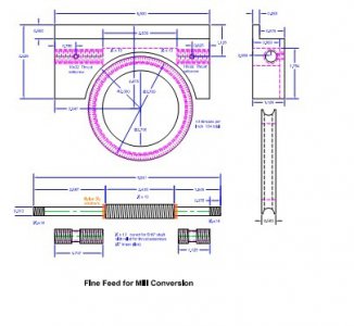
I modified the design to allow for eliminating the backlash in the worm gear. I cast mine from a ZA27 alloy that I mix but it could be cast from aluminum just as well. I turn the ring gear and thread it using a tap as a gear HOB. I have gone to using spiral taps as hobs because there is always a thread in contact with the gear . You don’t need to scribe the first set that way.
d-m ring gear perimeter cutting.jpg[video=youtube;WXZb3M9Y_Yo]http://www.youtube.com/watch?v=WXZb3M9Y_Yo[/video]
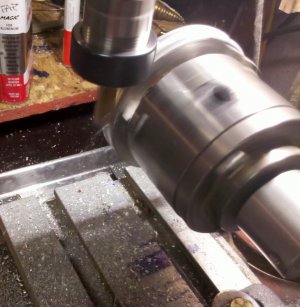
This picture is using a 7/16 mill to cut the cove for the thread in the ring gear. The ring gear is mounted on a 3 jaw lathe chuck that is in turn mounted to a live center and held in the vice. My live center is designed with a ½ x 20 thread for the cones. It allows me to remove the cones and mount chucks etc to the live center for this type of application. My live centers uses a small double row angular contact bearing. By bringing the mill down to the tangent point it cuts and drives the ring gear.
m-d fine feed ring gear hobbing.jpg[video=youtube;a_-3Or2SF3Y]http://www.youtube.com/watch?v=a_-3Or2SF3Y[/video]

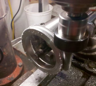
As you can see in this picture this also works with the tap when placing the threads in the ring gear. I turned the tap at about 60 rpm and started with the taper just above the tangent point and feed the tap down until it was turning through the taper and on the full tap. I then run the rpm up to about 550 for a minute or so and allowed it to clean up the threads.


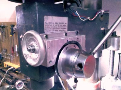
The ring gear is mounted to the drill press ring that was used for a quill stop. This allows the fine feed to be disengaged vary easily when you want to use it for a drill press. The ring gear is bonded to d-press ring with Locktite bearing adhesive.


drill-mill fine feed.jpgfine feed.jpg

The worm gear is a piece of ½ x13 threaded rod that has been turned down to 5/16 on each end where it goes through the housing. The housing is bored and threaded ½ x 13. The bearing surface inside the housing is made by taking a 1/4" brass nipple and threading the outside and cleaning up the inside bore for a bearing. These can also be adjusted to remove the backlash from the worm gear. I use this bearing method most times on items that need a worm/ring gear set. It also acts as a hard brake on ring gear travel. The worm gear on this also extends beyond the housing for the attachment of a z axes drive. I normally just put my vary speed drill on the hand wheel bolts for rough setting and quick moving. I have short videos of cutting the ring gear that I will put up once I figure out how.


The next set of modifications for this conversion will be to add external springs to the quill. The reason for this is that the spring that is currently lifting the quill is on the pinion which leaves the quill floating. The external springs will force the rack against the pinion and the fine feed will then be in direct down contact with the quill The weight of the quill and the springs will prevent the end mill form walking in most cases.

The installation of Gibs to the quill will remove the play that is between the head and the quill. At that point you will be able to raise and lower the quill under light cutting loads such as a boring bar, heavy loads like a face mill would still require locking the quill in position.

On this conversion I will use the center Gib screw to lock the quill.

I’ll address the motor changes and the control that I use on the mill and lathe in the next post hopefull next week.


That’s about it for this portion of the post. I have had to back burner this project as the process of meeting my Aluminum ingot sales has really pushed me. Since Christmas I have designed and built a tilting furnace, and torn down and melted enough transmissions and outboard motors to generate 550 lbs of aluminum, I finally have got my ducks in a row so that I can do a 50 to 75 lb run in a day and not be dead for the next three days. I quit using transmissions and started buying 90% of my aluminum already torn apart. It took longer to tear the transmissions down then it did to melt and ingot them buy about triple.

d-m ring gear perimeter cutting.jpg m-d fine feed ring gear hobbing.jpg drill-mill fine feed.jpg fine feed.jpg fine feed.jpg
 
Last edited:
very ingenious use of a spiral tap to cut a gear, nice job!
 
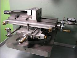
Asian X-Y table modifications

converting-drill-press-mill-drill-x-y-1.jpg

For this conversion I was able to locate an early American made table that I will install a set of DROs on. When I am not able to find an American made table and must use an Asian table, there are items that need to be modified to bring them up to par. They are excellently described on Nick Carters site. These explanations are from that source. I have excerpted pictures and some of his write up. His site includes how to do the modifications on the leadscrew. This material is being used with his permission.
Source Cross-Slide Table Modifications I have made my comments in blue
+


Gibs Not necessary but i use brass gibs whenever possible
The original gibs were steel and not suited to wearing in for that nice silky movement. I just made exact duplicates in brass. Over time they have improved the action noticeably.

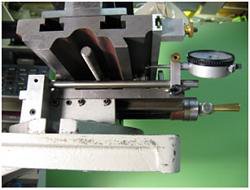
Dial Gauge Control for Table Movement this is replaced by the DRO

With the poor leadscrew dials it was just about impossible to move the table with any precision. Since I wanted to drill accurately located holes, this was important. I tried mounting dial gauges with magnetic bases and arms but found it surprisingly difficult to get them placed just right. Constant headache. So here's my solution.

converting-drill-press-mill-drill-ph-3.jpg
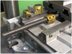
Photo 3: Y-axis Dial Gauge


Photo 3 shows the mounting blocks and rods installed to hold dial gauges for measuring table movement in the X and Y directions. This eliminates any uncertainty because of backlash, loose gibs or a sloppy lead screw.


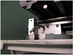
Table Locks
Locating the table precisely is not much help if it's going to jiggle around whenever the tool hits the work. So locks are needed to make sure it stays put.

converting-drill-press-mill-drill-ph-5.jpg
Photo 5: Y-axis Table Lock

Photo 5 shows the extra gib holes drilled and tapped to take the ball handled locking screws. Once tightened, these keep the positioned table perfectly stationary. Very accurately spaced holes can be achieved.

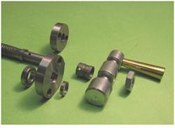
Thrust Bearing This improvement is almost a necessity

I wanted to try light milling on the drill press since I didn't have a milling machine at the time. Experiments showed that there was just too much uncontrolled table vibration. For milling, the table should be as jiggle free under movement as when locked down. Once the gibs are properly adjusted, the only other component allowing uncontrolled motion is the lead screw. I started with the thrust bearing where I assumed (incorrectly) all the backlash to be.

converting-drill-press-mill-drill-7.jpg
Photo 7: Original and New Thrust Bearings

converting-drill-press-mill-drill-8.jpg
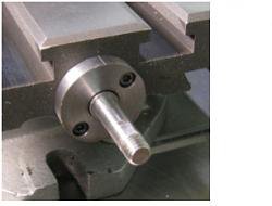
Photo 8: Mounted New Thrust Bearing

The original was just a steel disc with lots of non-adjustable backlash determined by how (not very) close to it the outer sleeve was pinned to the shaft during manufacture. The new one carries a ball bearing and spacer so the backlash is determined by the precision of the ball/race fit. If I were doing it again, I'd make this block thicker and mount two ball bearings with a spacer between and some bearing preload. It's amazing how much play there is in a single ball bearing. I never thought of this until later but couldn't have done it originally anyway because I was fitting it to the original leadscrew and was limited to the thickness of the original thrust plate.
The new plate had to be larger in diameter to make room for new mounting holes outside the bearing recess.

Leadscrew and Nut This improvement is almost a necessity
The new thrust bearing helped but didn't completely eliminate the problem. The table could still be moved perceptibly back and forth. So I took the whole thing apart to have a look at the leadscrew assembly.
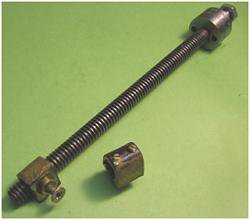
The original leadscrew has a 1/2-10 Acme thread and a very loose nut. The second nut in Photo 9 shows how I tried to tighten up this fit by adding screws to bear on the leadscrew. It was a half-vast fix and didn't really work. Making an adjustable nut for an Acme thread is problematic and, anyway, the cost of a 1/2-10 Acme tap is close to $100. So back to the drawing board.

converting-drill-press-mill-drill-9.jpg

Photo 9: Original Leadscrew Assembly


Here is the heart of all these modifications, a new leadscrew and nut. The leadscrew is 1/2-20 threaded rod and the thrust bearing end was machined completely on the Taig lathe. For some reason, at the time of making this particular part I made step-by-step photos which are in the appendix for those who are interested. The nut is adjustable following the practice of the Taig CR mill and is somewhat larger than the original which is shown for comparison. Also shown is one of two spare blanks made in case of a screw-up along the way.

converting-drill-press-mill-drill-10.jpg
Photo 10: New Leadscrew and Nut Assembly

Dials and Handles Nice improvement but not necessary with DRO
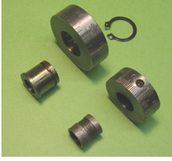
The original dials were intended for a 10 pitch leadscrew and were too small. The new ones have 50 divisions to suit a 20 pitch leadscrew and are the same size as the new thrust bearing carrier.

converting-drill-press-mill-drill-11.jpg
Photo 11: Original and New Dials

converting-drill-press-mill-drill-12.jpg
Photo 12: New Dial Mounted

The dial carrier was made the same length as the original pinned spacer. The new dial is held in place by a circle clip which is bent and rides in a groove wide enough to let it press lightly on the dial so as to damp its rotation.

The increase in leadscrew pitch means more turns per inch table travel so rotating handles ease the wear and tear on fingers.


Again I would like to agknowledge that the above post is located @ Cross-Slide Table Modifications in its complete form. The details for makeing the Lead screw are at that location.
 
Column and the spindle Gibs

I have had a few requests for an explanation of the column and spindle gibs. I havn't gotten to that part of the conversion partially because it takes a complete tear down and some time and... '[;.,/ ... to get them in

The gibs when installed and adjusted remove the slop that is in the drill press head that causes much of the frustration found in using a converted drill press even when the bearing issues are removed and the column filled with cement etc..

This modifaction is what allows a face mill to be used and still have a clean surface, I have run a 3" face mill with out issues with the gib modification completed. The manufactured mill-drills are machined to a closer tolerance then the drill presses are and without this mod you can never get the quality cut that is available in the higher end mill drills. You may find that the brass bolts mentioned at the end of this write up that are used in the interm while makeing the gibs, may work for you if you aren't going to use face mills or large diameter boring activities.

I have tried a couple of different positions on the gibs. I have found that the very back of the column is the best location for the column gibs and the very front opposite the pinion on the spindle. The design is the same for both.


I have tried a 120[SUP]o[/SUP] separation using 2 gibs on the column but have found that it must be almost perfectly adjusted or it cants the head and makes it very hard to keep the machine trammed. I do use it on the column if I cant reach the column lock that is in the center of the Gib I then use the 120[SUP]o[/SUP] gibs with the one that I can get to as the column lock.

in the drawing above there is a second gib above the journal. On some of the larger heads I have had to add that Gib in order to get the last of the forward slack out of the head. This conversion is a 17" head and that is about where I end up using the upper gib as well as the lower one. I have found that it isn't a good idea to place the lock screw in the upper gib. I cut the gibs .125 shorter then the total space between the journals and I have made the column gibs from the old lift rack successfully. I have also made them out of brass if using a head with a short quill travel.

I make the spindle gibs out of brass as they are moving a lot more. The method I have used to cut the cove to match the spindle diameter is to mount the brass casting up against a block in the mill vise. As a gib in the interm I use a brass 5/16 bolt in the whole in the front of the head that will later be used as the quil lock. This could be done on the column as well but you would definatly need to place one above the journal in that case.

I will add pictures to this write up as I proceed with this modification but this will help anyone that is in the wondering mode about the gibs.

Till next post


Art
 
Last edited by a moderator:
Back
Top