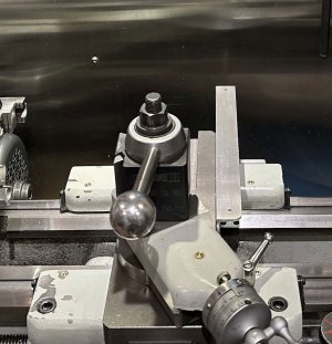
DRO magnetic scale installation question

BTW - M DRO also sells the tape separately. That could be stuck to the cross slide itself for a very low profile installation.
The tape I used inside the extrusion can be used in that fashion, one side of it has a non-stick strip which, when peeled off, exposes the adhesive. Even though the system says it "cannot be contaminated", I'm not confident it would survive for very long having a chip or two enter the gap, especially on the chuck side of the cross-slide.

Another consideration is the system requires the magnetic strip to be 60mm longer than the travel distance of the head, this to accommodate the read head's length. While the cross-slide length on my lathe offers a net 85mm or so of overtravel distance, the positioning of the read head on the carriage would be more constrained. I haven't checked to see what I'd have to work with, but I will, wouldn't be the first time I moved a DRO sensor ;).
 
Yes, chips in the gap will cause misreads. You need some type of chip protection. I am just surprised that they chose to mount a 10 mm wide mag tape in a 1" wide aluminum housing. Rigidity I guess? Still that creates issues on small machines. A simple aluminum L or U just large enough to carry the tape would be fine.
Here is how I mounted mine. I still lost 1" but it has not been a problem.
 

Attachments

  • dro-cross.jpg
    dro-cross.jpg
    127.1 KB · Views: 21
That mount on your lathe looks great!

I'm going to revisit mine...

Things I recall when I installed the glass scales on the TS side were:

1) Interference with the 3 cross-slide gib screws, somewhat mitigated by using a ball-end Allen wrench.
2) Loss of direct tailstock to carriage contact, never a game-changer but an annoyance, especially when using the TS for keeping a threading die in place, I'd run out of quill extension before the threads were fully through the die sometimes.
3) Interference with the compound itself, or the handwheel with meant removing the scale, then reinstalling it.

While mounting this system on the chuck side eliminates all of the above, it has it's own potential issues as we've already discussed, it's always a matter of the lesser of the evils I suppose.
 
Well summarized. I can see you have thought this out. You can see from my pic how far I had to project out the scale so I did not cover the gib screws or the compound rotation lock. I kept the top of the scale mount at the level of the cross slide so it would never interfere with the compound or mounting of accessories on the far end.
 
After reading the technical specifications on this magnetic scale more thoroughly, I came across a feature I don't fully understand, noted in red below:

1 - 1 Micron Resolution Magnetic Encoder - Compatible with M-DRO high accuracy magnetic tape - DRO-MG-TP-05-HA
2 - Compact Reading Head - A very compact and robust sensor head
3 - Non Contact System - No moving parts and no contact to magnetic tape, no wear
4 - Robust Construction - Sealed aluminum sensor housing with heavy duty flexible armoured cable
5 - High Speed Operation - 60m/min reading head speed
6 - Reference Signal - A separate magnet can be set at the required position to provide a reference position
7
- Applications Include - CNC or Manual machine tool position, automation and assembly equipment, woodworking, stone/metal cutting, sheet metal guillotine, bending/folding machines
8 - Resolution - 1 micron (0.001)
9 - Max read speed - 60m/minute
10 - Working temperature - 0 ~ 85C
11 - Head dimensions - L52 x W10 x H17mm
12 - Cable length - 3 metres
13 - Output signal - 5v TTL Quadrature

I have asked the distributor about this, they are checking with the manufacturer. Nowhere in the technical drawings does it show how to physically enable a reference with an external magnet, nor how that mark would be exposed in software to make it useful in a DRO context.

Figured maybe someone here with more machinist and/or DRO experience may know how a feature like this works?

Thank you.
 
Back
Top