Electronic Lead Screw Mod

It’s a stepper, same one clough42 used. He ended up going to a stronger stepper (one with a servo built in if I remember correctly) and as much as I’d like to follow suit, I’m just not ready to attack that just yet. I want to use my equipment more than I want to tinker with it anymore. TBH it’s a few steps above my comfort zone.
You have that a little twisted. A stepper is a simpler and different device than a servo. No stepper has a servo built in. He is using the same servo I am, the iSV57T-180. This servo has an integrated controller, so it is simpler than a stepper motor. To replace the stepper with this servo, just remove the stepper and the controller, and install the servo, driving it directly from the ELS board. If you are not currently using a speed reduction gear or belt, that would be desired.

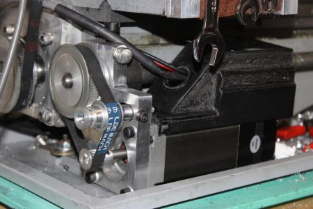
I am not sure why you say it is above your comfort zone. The machining was easy (90% on the mill), and installation was a snap.

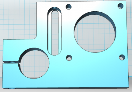
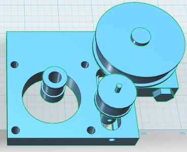
Here is my solution:
 

Attachments

  • Servo plate raw.PNG
    Servo plate raw.PNG
    91.1 KB · Views: 32
  • Servo plate.PNG
    Servo plate.PNG
    148 KB · Views: 31
  • lathe servo.jpg
    lathe servo.jpg
    100.6 KB · Views: 26
Last edited:
I am using a Nema 24 hybrid stepper with a 1:1 pulley ratio and 2:1 gear reduction in my gear box. The stepper and driver will monitor lost steps and attempt to recover them up to one revolution. Beyond that, it throws an error requiring a reboot of the driver. My driver is powered separately from the rest of the ELS circuitry so I only reboot the driver. The Stepper is rated at 4.25Nm of torque at a driver voltage of 48 volts and I am driving with 42 volts. I measured a force at the carriage of 110 lbs. at a driving rate of 3mm/rev. and a spindle speed of 300 rpm.
There is no gearbox on my lathe, but I am using a 4:1 timing pulley and belt reduction.
 
@lesrhorer I am getting it twisted. I remember the Clear Path motor having something built onto the end of it (I know he ended up going a different manufacturer as it was titled "Clear Path Killer" or something along this line), and the conversation of constant feedback, I took this as a servo. There are a few lines within the code as far as pluses/steps and maybe 1 or 2 other things, honestly getting into the code and knowing what to change is the most PIA part. At any rate, a bit stronger stepper needs to be in my future plans.
 
Honestly, modifying the Configuration.h configuration header is beyond trivial. For most users, the only lines that need to be changed are:

Code:
// For Imperial leadscrews: pitch in Threads Per Inch (TPI)
//#define LEADSCREW_TPI 12

// For metric leadscrews: pitch in hundredths of a millimeter (HMM)
// Example: 200hmm = 2mm
#define LEADSCREW_HMM 200

// Steps and microsteps
#define STEPPER_MICROSTEPS 4
#define STEPPER_RESOLUTION 1600

// Encoder resolution (counts per revolution)
#define ENCODER_RESOLUTION 4096

Some folks might need to invert some of the pins, especially when using gears instead of belts. In my case, I have a 2mm pitch lead screw, so I set the LEADSCREW definition to HMM 200. The servo is set to 1600 pulses / rev, but I am using a 4:1 reduction, so I set the microsteps to 4 and the resolution to 1600. (Ordinarily, I could have set the resolution to 6400 and the microsteps to 1, but the maximum value allowed for the resolution is 2000, so I split the product between the two.) I am using the same encoder James is, so I left the renoder resolution at 4096.

I definitely recommend a servo, rather than a stepper. Using an integrated servo like the iSV57T series means eliminating the controller altogether, making things simpler, and with a servo, one needn't worry about lost steps. Why complicate your life?
 
Hi all
i have just found this thread because I have bitten the bullet and ordered the full kit from Rocketronics in Germany and was doing research on the electronic leadscrew and crosslide .
I had been looking at doing it because I have gout in both hands so they are not very good but I can still press buttons, eyes not as good as they used to be either.
the kit has a closed loop stepper with integrated encoder so no lost steps, it not only allows threading metric, imperial, and BA although for the Imperial convert tpi to metric but I understand that the imperial software upgrade is being tested at the moment, also taper cuts, boring, internal threads, taper threads both internally and externally plus many other things.
I am still waiting for the kit to arrive so not able to do to much but I have made the bracket for the stepper motor and it will fit very nicely in between motor and headstock using original motor mount bolts so no drilling , the encoder for the spindle will fit where the change wheels were ( hopefully), I had ordered some pulley’s but they were crap so are going back and have ordered more from another company , I have a electrical cabinet for all the electronics plus some other bit and bobs ready for when the kit arrives, the display is in German and English.
I will start a new thread when I get going properly.
D47A2DD1-96A5-47BF-86B8-4B8F49D4CF22.jpeg
EA0BC8EC-45E3-440B-BDBA-BF86978F7950.jpeg
2DB24BB2-2B8D-4DE5-AE87-ABFE48260E6C.jpeg
D673DFA4-A475-4CD9-8805-56585197E38E.jpeg


Yes I know there are to many holes in the base plate but we all make mistakes, and as it’s only the base plate I am not to worried.
Dell
 
I have two things to contribute here. I could one of the controllers used for the lead screw also control the spindle motor? My vevor 7x16 has complete ass control of the bldc spindle at low rpm because it only has 4 ppr “encoder” for control. I’d love to feed it the same resolution as the eld conversion, so it wouldn’t hunt up to 600 rpms at the start of the cut when I’m trying to thread steel at 240 rpms. And with spindle control it would be really easy to stop at the shoulder.

The second thing, why do you need to stop Z within 5 tenths when threading to a shoulder? You should have the entire width of your grooving tool to stop, you are making an under cut when threading to a shoulder right?
Yes undercut when threading upto a shoulder, The Rocketronics controls both the leadscrew stepper motor and the crosslide stepper so when thread cutting you just input -Z whatever length thread you need, total depth of cut in -X press start it will show how many cuts but you can alter that if you want press start again and it will cut the thread , at the end I do 1 or 2 spring passes to clean thread all you do is press start again and set number of cuts to 1 and start again.
Dell
 
Strictly speaking, if one undercuts the thread near the shoulder, then one is not threading to the shoulder. OTOH, also strictly speaking, only a very advanced lathe like a Hardinge HLV lathe that can retract the tool almost instantly can truly thread to a shoulder. Even low cost CNC lathes will have trouble with this to a certain extent unless threading at low speed. All that said, losing 1/2 a thread at the shoulder is more than good enough for most jobs, and an ELS can easily manage that. While virtually any human operator will need at least a small undercut, the ELS makes it unnecessary if it is programmed to stop at a given point. Even at relatively high speed, the ELS is more than capable of stopping the carriage very quickly and accurately, making an undercut unnecessary.

Turning to a shoulder is a completely different matter. One must always ultimately stop the carriage very accurately when turning to a shoulder, but it is also an easy thing for even a human to accomplish, since the carriage and the spindle can be uncoupled when the tool nears the shoulder, and the tool can then be advanced very slowly, no matter the spindle speed. With an ELS, the spindle and the carriage are always decoupled, so turning to a shoulder is a trivial operation with an ELS, whether automated or not.

Finally, there is no need to stop or slow the spindle at all at any time when turning or threading with an ELS if it is properly programmed. Maintaining a constant RPM is another matter entirely, and does not need to be coupled in any way with the ELS.
 
Hi all
i have just found this thread because I have bitten the bullet and ordered the full kit from Rocketronics in Germany and was doing research on the electronic leadscrew and crosslide .
Nice work. A cross slide control would be very nice, but I will be more than happy to settle for start / stop programmability on the lead screw. Actually, I do intend to install a stepper on the cross slide to make it faster, easier, and more accurate, but I don't intend to tie it into the ELS system. I just want to control it with a manual rotary encoder.
 
Nice work. A cross slide control would be very nice, but I will be more than happy to settle for start / stop programmability on the lead screw. Actually, I do intend to install a stepper on the cross slide to make it faster, easier, and more accurate, but I don't intend to tie it into the ELS system. I just want to control it with a manual rotary encoder.
I haven’t found any limitations to the Rocketronics as yet it will do everything I need , there is buttons on the controller to turn the stepper’s off and it has fast & slow buttons for the stepper’s & I sometimes turn using the slow buttons if I just want to remove a small amount of material, I needed to make a tool rest recently for my Pultra lathe as I only had a 50mm height one & my Pultra is 70mm so I set the parameters in the elliptical setting in control and away it went.
Dell
IMG_1932.jpeg
IMG_1961.jpeg
 
Back
Top