Flash cut cnc Induma hybrid Bridgeport helped

Hiya2u5

Registered
Registered
Joined
Oct 1, 2020
Messages
3
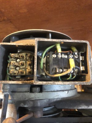
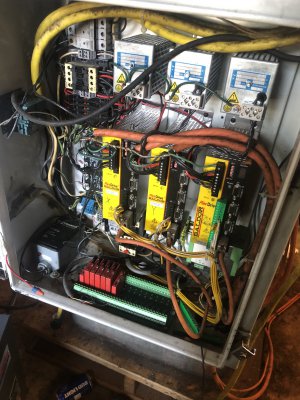
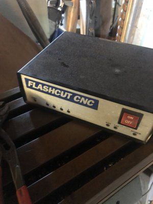
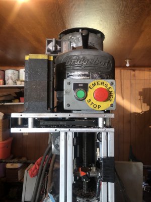
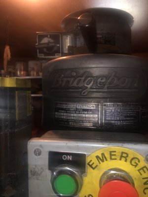
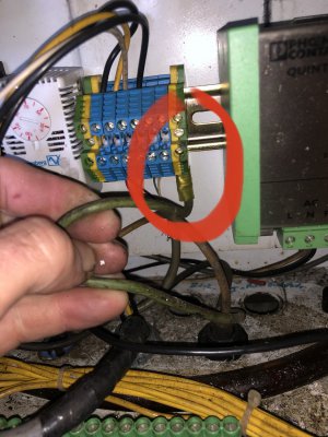
I recently purchased a Induma/Bridgeport mill. It supposedly was operational a year ago. It has been converted to flash cut cnc. The wiring is a nightmare to me and I can’t figure anything out about it. Im hoping someone can recognize something and help me out. I have a rotary phase converter. Basically what is throwing me off is the Motor has 3 wires coming out of it black green and white. The green seems to be ground which makes no
Sense to me.BBC2E012-8A7F-478B-ADD9-5F737856559C.jpeg887EFB4B-1B81-4912-827C-02F883D8CD8E.jpeg1CCC0D11-2961-44D8-BF51-FA2C448EAFDF.jpeg24B43774-5223-4A28-81A4-11AD7C52EE1C.jpegFFF2AB1A-2B54-4B8E-BF44-42AAD44614D7.jpeg197D76D8-3651-4C6E-AE69-4591CE4D70F3.jpeg
 
Normally in wiring green would be ground. It looks like in this case it is one of the hot legs of three phase circuit with the other ones being white and black. No wonder it is confusing. Maybe it was done so as to use a standard 115 volt cord 3 wire cord to supply the Three phase to the motor. Use care in untangling this wiring job and stay safe. I would rewire with a 4 wire cord so there would be a ground and 3 hot legs. No ground would not be the safest thing .
 
Last edited:
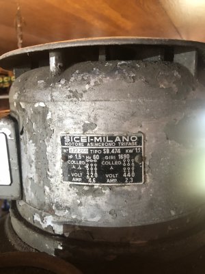
Your correct about the green wire. It does not appear to be a ground wire. In your second picture, it appears as the motor is wired for 220v. The terminal block on the left hand side of the pic matches the nameplate in the first picture. The small green wires that jump the terminal block to the switch are your motor leads. The power will just pass through the switch to the motor.
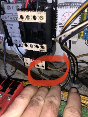
You need to determine which contacts are closed when the switch is in the fwd direction and which are closed in the rev direction. That will determine where the blk, wht, and green wires go. the switch will "swap" two of the power phases to the motor leads that switches motor rotation.
It appears to be correct to me. In reference to the second photo, If you look at the contacts right to left, the first contact is closed with the switch in both FWD and REV positions.
The Second and Fourth contacts should be in the same state as each other, either open or closed. The third and fifth contacts should be in the same state as each other, but opposite of the second and fourth contacts.
I would guess the other end of the BLK, WHT GRN cord connects in the control box to a T1,T2, and T3 terminals.....
 
I have nothing to add except, Welcome to the group @Hiya2u5 !

....well okay, one thing........although that wiring is a mess, at least it seems to be built with quality components.

Good Luck!
-brino
 
The issue I’m running in to is if I put an ohm meter on the green wire at the switch or in the main box and the other lead to any where on the machine tbere is continuity. I agree the green wire in this case should be the third leg of the motor. It appears it’s been wired like this for a very long time. Nothing looks tampered with thst I can spot.
 
Here’s the wiring coming out of the main power box going straight to the switch for the motor. Green going straight to ground.1196D431-56D0-403C-AA7D-36A3772B471D.jpeg50B3D2BA-3A2D-4E01-91FD-BF051485A26F.jpeg
 
I have this same motor, on my induma 1-s. I got it wired up, but it sounds like you're getting better help than i can give on the electrical side. I'm always looking for Induma owners, I started a small facebook group dedicated to this machine, since i couldn't find any other dedicated resource. (You can find it if you search for it).
 
Back
Top