Freeport 6 X 18 help

KWGeorge

Registered
Registered
Joined
May 2, 2018
Messages
10
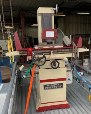
Hello all! I am hoping you can help me with a question (more to come later) I purchased a very little used circa 1990 Freeport 6X18 Surface Grinder. I believe the model # is SGS-8618B but it is hand engraved on the plate so I am not sure. I have disassembled most of it and am cleaning it up but when I bought it unfortunately they lost the tools that came with it. I have noticed like a lot of Asian tools this has been branded by many importers.


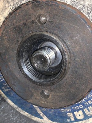
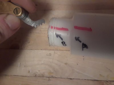
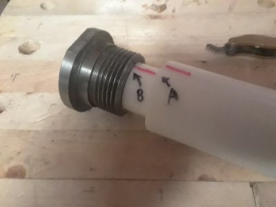
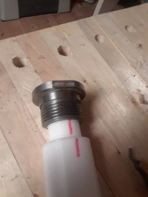
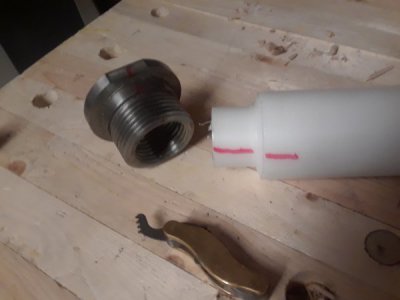
What I need at this point is what I believe is called a Wheel Extractor by some company. However I can’t find one for sale so I guess I will have to make one. It appears to me that it will require a puller with an external M25X1.5 thread and then an internal thread for a bolt to draw the wheel off. Could someone who owns this machine or a clone validate the external thread size for me? Please? :)
 

Attachments

  • IMG_5305.jpeg
    IMG_5305.jpeg
    67.7 KB · Views: 119
  • IMG_5347.jpeg
    IMG_5347.jpeg
    94.8 KB · Views: 135
The hubs for the wheel are often made by another manufacture, there is no industry standard compelling them use a standard thread to the given taper. The Harig and boyar schultz I have poses interchangeable hubs, but not the knock out tool. Your estimation of the thread is a good start to identifying the thread. A trick to identifying the thread pitch is to make a plastic tube of an OD just larger than the minor diameter, push and twist it into the thread to form a thread, once established give the tube a whole number of turns while measuering the progression. This will give you the lead of the thread and with a little math it is a precise way to identify the pitch whether it is metric/inch.
 
Alexander, i think I like your resolution to this problem using the plastic pipe but i need some further help if you wouldn't mind....

Could you give an example of how you do the math that converts the pipe rotation into thread pitch numbers please? I assume you are not just counting the thread spacing but also the amount it advances per full rotation and thats where i start to fumble the ball and would appreciate your future assistants, thanks.
 
The hubs for the wheel are often made by another manufacture, there is no industry standard compelling them use a standard thread to the given taper. The Harig and boyar schultz I have poses interchangeable hubs, but not the knock out tool. Your estimation of the thread is a good start to identifying the thread. A trick to identifying the thread pitch is to make a plastic tube of an OD just larger than the minor diameter, push and twist it into the thread to form a thread, once established give the tube a whole number of turns while measuering the progression. This will give you the lead of the thread and with a little math it is a precise way to identify the pitch whether it is metric/inch.

Thanks for your reply to my question. I should have update this to say I found a puller that worked as my guess on size and thread pitch was correct. I found that a Motorcycle Flywheel Puller of this size works great to take this off. I was going to make one but then the one I found was just $9.
 
I tried making a demonstration on my Harig to determine the thread pitch, though the small diameter and fine threads were too fine to see effectively on camera, so instead I will use this Southbend to Logan adapter. Pretend we don't know what the internal thread dimensions are, or what this fits. First we measure the minor diameter with our calipers and find that it is roughly 1.375". That tells us vary little as this will change dramatically should the thread be to 50% or 75% thread engagement or be metric. For major diameter we can try to measure the out feed of the helix to estimate the major diameter, obvious this an obtuse measurement to take with any measuring tool and depending the the sharpness of the tool cutting the root this can vary dramatically, and it apperas to be 1.4375 to 1.5625..

So now lets check the pitch. You could well use a a thread pitch gauge (the brass swiss army knife thing shown), but these are best suited for external threads as visibility is key, Doing so it shows this to fit well with both the 8TPI and 3mm gauge as they are off only by .007'' per revolution.
In the metric system they measure pitch as mm from thread to thread, know as the Lead of the thread as far as single helix threads are concerned. (Lead is progression of a thread for one whole turn) While the imperial system uses threads per inch. 1"/pitch gives you the lead for imperial threads with a single helix (1"/tpi=lead). So in this example below I made a 1.385" diameter shoulder on a piece of UHMW, (any other soft yet firm materiel will work) and added the marking with a paint pen. I twist and force the threads together till I get the helix to reveal itself. I thread it on as far as I will go comfortably, (I should have used less interference) measure A to B, revolve one turn and measure A to B again. It shows .125'' progression per rev. For a finer thread I would use 10 revolution then divide the progression by 10 to get the lead. This is because the error of you measuring tool is generally consistent over a small or large range, and the error in clocking the thread is divided by however many threads you used. We can now divide 1" by lead to get pitch. (1"/0.125")=8tpi. Now we look in the book and find that these are characteristics of a 1 1/2-8tpi thread, and sure enough this is common among mid sized American lathes spindle.
 

Attachments

  • 20190907_090504.jpg
    20190907_090504.jpg
    24.1 KB · Views: 108
  • 20190907_090434.jpg
    20190907_090434.jpg
    27.1 KB · Views: 115
  • 20190907_090320.jpg
    20190907_090320.jpg
    29.6 KB · Views: 112
  • 20190907_090104.jpg
    20190907_090104.jpg
    27.8 KB · Views: 109
Back
Top