- Joined
- May 10, 2012
- Messages
- 995
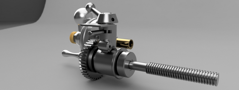
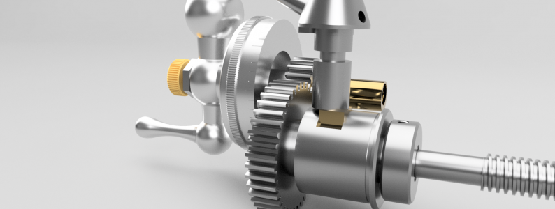
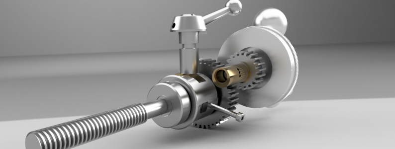
I've had the G.H. Thomas book "The Model Engineers Workshop Manual" for quite a while now, and I've read it completely a couple of times, and sections of it more than that. One section includes a design for a retractable topslide for a Myford 7" lathe. I like the design, and the concept, which makes threading much easier. I have wanted to incorporate one on my 12" Atlas/Craftsman "Commercial" lathe for some time. Doing the model is the first step towards that end state. I first did the G.H. Thomas retractable topslide (partialy) so I could get a more detailed idea of how it was designed than the text gives. To that end, I have completed the model in Fusion 360. There were some changes I made to the originals design intent that I will go into here. This design directly uses some of the parts from the GHT design and uses the handle and handle nut from the Atlas. The changes I made were as follows:
1. The leadscrew uses deep groove ball bearings instead of bushings to allow some preload to eliminate once source of backlash. It should also give a somewhat smoother performance.
2. It has the provision to have a 2:1 gear ratio so that you can halve the speed of the topslide movement relative to the input shaft. This was done mainly to make the micrometer dial easier to read, as it is only slightly larger than the factory one. This has the negative effect of requiring twice as many revolutions to move the topslide as before. The design is such that this can be easily changed to 1:1 by swapping the 40:20 tooth gears for 30:30, in case I don't like it.
3. It uses 3/8" thick gears instead of the 1/4" that the GHT uses, this gives more engagement when the topslide is retracted. The design of the gearcase is has been changed to allow for the additional thickness
4. It incorporates a backplate. I wasn't sure that the bearing sleeve and nut would clear the internals of the topslide, so I designed this to eliminate any problems that might have occurred. The design of the custom leadscrew takes this into account.
It is, besides the aforementioned changes, functionally the same as the GHT version. One other thing that could be done is to add a bushing in the gearcase and make the input shaft eccentric from bronze to give better bearing surfaces to the input shaft. Below is a render. I still need to do a little work to clean up the internals and complete the mechanism that locks the micrometer dial.


It may be a while before I get around to actually making this, as I have a lot of other stuff in front of it. I'll probably 3D print the more difficult parts just to make sure that I haven't done something with the design that I will regret in use. It's easier to reprint prototypes than it is to machine them. Take care.
1. The leadscrew uses deep groove ball bearings instead of bushings to allow some preload to eliminate once source of backlash. It should also give a somewhat smoother performance.
2. It has the provision to have a 2:1 gear ratio so that you can halve the speed of the topslide movement relative to the input shaft. This was done mainly to make the micrometer dial easier to read, as it is only slightly larger than the factory one. This has the negative effect of requiring twice as many revolutions to move the topslide as before. The design is such that this can be easily changed to 1:1 by swapping the 40:20 tooth gears for 30:30, in case I don't like it.
3. It uses 3/8" thick gears instead of the 1/4" that the GHT uses, this gives more engagement when the topslide is retracted. The design of the gearcase is has been changed to allow for the additional thickness
4. It incorporates a backplate. I wasn't sure that the bearing sleeve and nut would clear the internals of the topslide, so I designed this to eliminate any problems that might have occurred. The design of the custom leadscrew takes this into account.
It is, besides the aforementioned changes, functionally the same as the GHT version. One other thing that could be done is to add a bushing in the gearcase and make the input shaft eccentric from bronze to give better bearing surfaces to the input shaft. Below is a render. I still need to do a little work to clean up the internals and complete the mechanism that locks the micrometer dial.


It may be a while before I get around to actually making this, as I have a lot of other stuff in front of it. I'll probably 3D print the more difficult parts just to make sure that I haven't done something with the design that I will regret in use. It's easier to reprint prototypes than it is to machine them. Take care.


