

- Joined
- Mar 5, 2012
- Messages
- 161
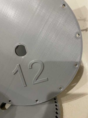
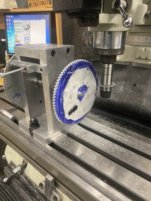
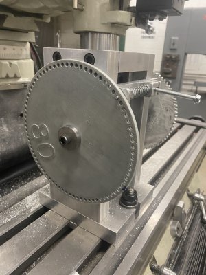
I am truly a hobby machinist and this is the first gear cutting jig I have attempted. Using my 3D printer, I can print multi-hole discs in about 10 hours. The filament cost is in the range of $2 per disc. They are attached to the arbor with a D shaped hole. After each cut, the disc will be advanced to the next hole by first loosening the retaining clamp (circled in one of the pictures). Thereafter, the disc is moved to the next hole and held with a spring-loaded pin. There is some very small back-lash, caused by the arbor being undersized (rookie mistake). Tightening the clamp holds it in place securely for the next cut. I haven't tested it yet, but may need to remake the arbor at a slightly larger diameter.
In addition to showing my work, I have questions about how to attach the workpiece. The plan is to cut large gears, 6.5 inches diameter with 80 teeth and smaller gears (12 teeth at about 1.5 inch diameter). Material will be aluminum or brass, in the range of 3/16 inch thick. Most likely, the small gears will need a small center hole and the large gears will need a larger center hole. Can anyone suggest a method to use this jig for various sized center holes? Initially, I thought I might simply drill and tap a small hole in the end of the arbor (1/4 inch or less) which would be used for every gear. Thereafter, I could enlarge the gear hole as desired using my mill. I am also somewhat concerned about securely attaching the workpieces, since they will have round holes. Do I need to be concerned about the workpiece spinning? Even a small amount would ruin the workpiece.
Would appreciate any thoughts and advice...
Thanks in advance
Jim
")