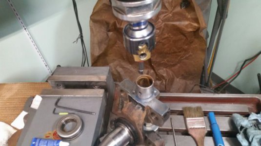
A friend of mine gave me a box full of tooling. These include many, many end mills of different shapes and sizes, t-slot cutters, reamers, broaches, expandable reamers, etc, etc, etc. These are worth a fortune and to top it all, most have never been used!
In return, however, he asked me to try and fix his M/Benz Vito's driving shaft. One of the universals seized and these prop shafts are not made to be repaired. There are no cir-clips on the yokes to retain the universals. Instead, they are punched, after the universal is installed. So, basically, you throw it away and buy a new one, or you can cut the existing yoke off and weld on a replacement.
Both the above options are ridiculously expensive, especially buying a complete new prop shaft.
He found a universal that has the same length, but the end caps are slightly larger in diameter than the original. My job is to attempt to machine the yokes out by 1.5mm to be able to accommodate the larger diameter universal bearing, but this doesn't look to be that easy.
Doing only one wouldn't be too much of a problem, but my common sense tells me that the two holes need to be perfectly lined up and then machined precisely and at the same time. Doing one at a time might, or rather will probably result in the two holes being slightly off center from each other, which would wreck the yoke.
Is this possible, or is the way to go to buy a replacement yoke and weld it on? How do I mount the yoke and how do I indicate both holes. I do have a center finder, but not a DRO.
Should I end up getting the yoke mounted, which tool and method would be best to machine with? A boring head or should I try to mount it in a large drill and drill it out to size.
I'm looking forward to any opinions and advice.


