How to wire 30yr motor w/no diagram

Kroll

Active User
H-M Supporter Gold Member
Joined
Dec 23, 2012
Messages
1,307
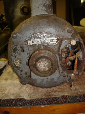
Guys as much as I like old machines I also like the old motors that come with them.And like the machine they come on they have their own problems,mostly wiring them correctly.I usually take them apart give it a good cleaning,replacing bearings and check the connections.I have this Century 1/2hp motor 1725 rpms that can be wired either 120/240 volts either CW/CCW rotation.It also has the centrifical switch w/thermal overloads.When I pick this up it had been setting for afew yrs and the history on it was limited/none,so I don't know if the PO had it wired for 220 volts or 120 volts but I would like to wire it for 120 volts.I did plug it in just to see if it would at lease rotate and it did but the terimal end of the motor got warm in just afew seconds,I have to say it does have some torque.If you will take alook at the pixs and see what you think?I ask Mr. Google for some help but not much help/hope,then again maybe I'm using the wrong words.So any advise,directions,diagrams,etc please send them my way.Thanks ---kroll

- - - Updated - - -

Here's a diagram of a motor that does not have the thermal overloads,maybe this will help to come up with a game plan---kroll
DSC02042.JPG DSC02041.JPG DSC02039.JPG Century Motor.jpg
 
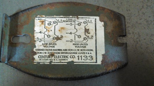
Kroll, that wiring diagram on the back of the cover does not go with that motor. It shows only 4 terminals, yet the motor has 5. You will need to trace the wires with an ohm meter to figure out what each one does.
 
I'd say it is the right diagram for the motor and the "5th" terminal is a mounting bolt.

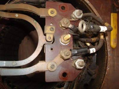
It appears to be wired in a different manner than either high or low voltage in the schematic. Note the copper wire as a "link" and the position of #5 next to L2.

I can see very few of the numbers but it appears as if someone was trying to reverse the rotation or something and got it wrong.

Steve
 
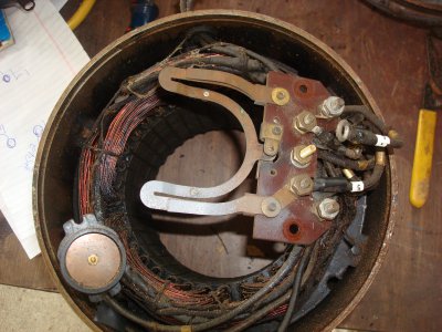
L1 and L2 are the incoming line and neutral, 2 and 4 are the start winding, which you swap over to reverse the motor. one of those is common with the run winding. However, I don't want to be negative about this, but that motor looks to be burnt out!, have you checked the insulation resistance with a megger ohmmeter? the stator windings in pic 1 look to be bare copper with the varnish burnt off! Check the insulation before you power it up.
Phil
 
Guys the wiring diagram is off another motor that does not have the thermal overloads.The three terminal screws all have wires on them on the back side.The wires are label #2,#4,#5 which I guess can go to either terminal screws for different configurations.thanks for the replys----kroll
Phil,I was kinda afraid of that,it did not smell burnt but it sure looks like it.Dang I was hoping that it was still good.

When you powered the motor up, did it spin? You say something about torque, but you never said it was spinning. If it was, clean the bearings, and you're good to go!

If not, you should take to motor to a shop. They will be able to tell you if the motor is indeed burnt out, and then if necessary they can re-wind the motor. If the motor is working, then they can help you wire it for the correct voltage.

-Cody

EDIT: After a close inspection, I still cannot tell if the varnish is burnt off of the stator windings, in left side of the first photo, or if that is just dirt.
 
I can see a copper wire linking the L1 and 5 terminals so it probably was 110...some of the other wiring looks wrong...Are the wires all numbered? 2&5 should be on L2 not the next terminal (B)as they appear to be. 4 should be on the one with a B. l1 should only have the line in and be linked to the next terminal....I just read that that is the wrong diagram?? OH Well, l2 still appears to be empty ...that makes no sense?
 
Thanks for the help,yes it did spin but the terminal end was warm after only afew seconds.At that point I know it works(but for how long) just need to figure out how to wire it for 120volts correctly.There is some varnish burned off where you see the shininess of the wire and I guess the black is the varnish that is burned.Maybe a trip to the motor shop tomorrow----kroll
 
Re: How to wire 30yr old motor

Thanks for the help,yes it did spin but the terminal end was warm after only afew seconds.At that point I know it works(but for how long) just need to figure out how to wire it for 120volts correctly.There is some varnish burned off where you see the shininess of the wire and I guess the black is the varnish that is burned.Maybe a trip to the motor shop tomorrow----kroll

The wiring diagram looks like the correct one for this motor. However the windings look burnt and should be meggered before trying to run. The SB 9" I just purchased had a motor that ran but smelled burnt. I bought a new one from Granger and had a real time with the wiring a reversing switch. The motor mfg. was kind enough to help with a proper diagram. You might check with Century
Best of luck, Chuck B
 
Kroll, that wiring diagram on the back of the cover does not go with that motor. It shows only 4 terminals, yet the motor has 5. You will need to trace the wires with an ohm meter to figure out what each one does.

It may be the correct diagram. Manufacturers sometimes show only the terminals that they think that the installer to needs to know about. The diagrams often also only vaguely resemble what is actually there.

Where is the capacitor?

I second tracing it out.
 
Back
Top