In TechDraw, is there a way to create a precise cosmetic line?

WobblyHand

H-M Supporter - Diamond Member
H-M Lifetime Diamond Member
Joined
Dec 18, 2019
Messages
6,447
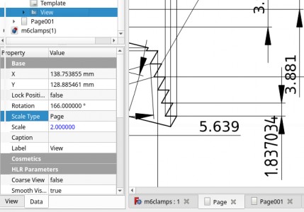
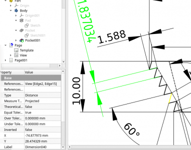
I've created a clamp that I'd like to machine. Having a bit of trouble dimensioning it in a way that I could machine the part. Basically, I'd like to create a cosmetic line that is exactly 104 degrees from the horizontal. There doesn't seem to be a way to easily do this in TechDraw. If I had such a line, I could dimension the distance from the vertices of the object to the cosmetic line. I can get an approximation to the angle, by hunting and pecking and placing a cosmetic vertex, and drawing a cosmetic line from the part to the cosmetic vertex. I need to get exactly 104 degrees, is there a way to do this? Or, is there a better way to accomplish something similar. Basically I want to mount the piece on a 14 degree angle and use a dovetail cutter. I need to know the offsets for the cuts.

Looking for some ideas. Thanks.
 

Attachments

  • hm_m6clamp_pg1.pdf
    195.1 KB · Views: 8
  • m6clamps.FCStd
    69.1 KB · Views: 3
I mostly have the concept of what you are trying to do, but my brain usually imagines things in a different way.

At first I thought you wanted measure angle/s, then it sound more like the step distance in those teeth.

First attachment is my attempt to dimension just one "tooth" after rotating, then I thought should be able to do that without rotating, hence #2.
 

Attachments

  • 1 Rotated 166.0.png
    1 Rotated 166.0.png
    54.1 KB · Views: 7
  • 2 as is.png
    2 as is.png
    88.4 KB · Views: 7
Thanks so much!

Yes, it's step distance. I will put the work piece on a ground angle block, but I need to know the step distance in Z axis. Also need the offset in the X axis. It seems I need to rotate the view like #1.png to get the local X of the dovetail cutter.

I was trying to do it unrotated and was getting confused. Could get the step to step distance, but not the orthogonal step offset. Need both to machine the piece.


I mostly have the concept of what you are trying to do, but my brain usually imagines things in a different way.

At first I thought you wanted measure angle/s, then it sound more like the step distance in those teeth.

First attachment is my attempt to dimension just one "tooth" after rotating, then I thought should be able to do that without rotating, hence #2.
 
Curiously, if one does a detail view of a part, one cannot rotate the detail view.

Even more curiously, if one rotates the view of the part, by 166 degrees, (placing the part as one would machine it) and then does a detail, the highlight circle incorrectly selects the wrong section of the part. Apparently this part of the FreeCAD code has a bug. In order for me to select the steps, I had to place the detail circle on the opposite end on the part. Worse than that, the detail view reverted to be unrotated, which is NOT what I wanted. FreeCAD clearly needs work here. Really didn't expect to run into this, ahem, feature.m6clamp_rotated.png

Eventually, I scaled up the view to 4:1, rotated the part by 166 degrees, and dimensioned it. Kind of awkward, but hey, think it will work.
 
in techdraw I had issues where it would show the measurements... then all of a sudden it would say corrupted and lose the values.
since the values come from underneath, how/why... very buggy. Freecad is very frustrating to me, after using sketchup and watchin fusion 360...
they seem more straight forward. but sketchup get complicated in it's way too.
Yes, I have experienced the same problems. Drawing is good, then "something happens" and some of the dimensions make no sense. Most of that is probably due to the topological naming problem, I suspect, which is slowly being solved. I have to add, that in my version (0.19), TNP is not solved. While a rather remarkable program, it is still a bit rough in some respects. Parts of the software aren't polished, or even complete, at least in my limited perspective. The version of FreeCAD I have is 0.19, which says something about its maturity. 0.xx software is not complete. It is still pretty good for all its limitations.

Fusion 360 doesn't run on Linux, which is what I use at home. Fusion 360, like other commercial CAD offerings wants a captive user, which I do not want to become. There's plenty of examples of commercial CAD programs changing the rules of the game to their advantage, and not the users. The amount of use I have in a year doesn't justify a license, nor would I want to pay for a license ten years from now to view my own IP then. So, I muddle along with FreeCAD. Seems to be the lesser of the evils.

As a beginning 3D CAD user, I find a lot of things to be hard. But it is getting a little easier as time goes by, and as I pick up a little more experience.
 
I would agree, I used FreeCad because using a software package that randomly changes the ground rules is scary, and license fees are primarily driven by commercial value. It is buggy and confounding, but it has a lot of potential, in, say, another 5 years. And it keeps the commercial CAD market grounded.
 
Back
Top