
My Grandfather was an EE, he couldn't wire a light switch!As you've discovered, all EEs are not created equal. It is hard to tell from the picture what you have going on there or what the intent was.
There are plenty of EEs that have never (and should never) touch anything over say 5 VDC.

-
Welcome back Guest! Did you know you can mentor other members here at H-M? If not, please check out our Relaunch of Hobby Machinist Mentoring Program!
You are using an out of date browser. It may not display this or other websites correctly.
You should upgrade or use an alternative browser.
You should upgrade or use an alternative browser.
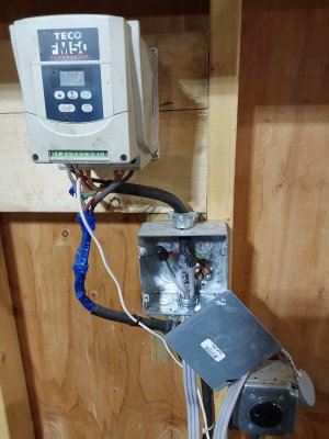
Is this wired correctly?
- Thread starter cgcwmec627
- Start date
- Joined
- Jan 2, 2019
- Messages
- 6,526
I used to have two EE’s reporting to me. Let’s just say there’s a wide range of understanding and practical abilities. Nothing can be said for sure other than an institute of higher learning conferred a degree on them, probably.
John
John
I think its the practical abilities that we take for granted. I went to a college with math and physics majors who were absolutely geniuses. I could not get over how quickly they assimilated the information the prof sketched out on the blackboard - stuff I struggled to understand. Yet, if you put these guys on a desert island with a case of canned food and a can opener, they would starve to death. On the other hand, I met a thermodynamics major who had designed his own engine. I met him in the school's machine shop while I was overhauling my car's engine. This guy was making his engine himself - from scratch - to demonstrate its features.
Yes, all professions are like this. There is a wide distribution of abilities in the human race. When I go to see a medical doctor about a foot problem what I really would like to see is what grade he got in courses on feet! There are some who got A's and some who got C's and D's but still got the degree. Then there are those who are got A's in dishonesty. There is a reason for malpractice suits and with these we get to select from a plethora of lawyers who have their own distribution of abilities and honesty....
Anyway, not all EEs should get a bad review just because there are some that may deserve it. So don't be to quick to be harsh on other people. They may know a lot about something else.
I was an EE and Physics major and a professor to taught these skills plus others. Power devices and transmission or things like wiring a house and motors etc. are only still taught in a few places. Not usually the schools where the EE graduates get the highest starting salaries. EE has become a very broad field and in my department it was not even called EE any more. The name was changed to ECE (Electrical and Computer Engineering) many years ago. As the name implies, programing, logic, control, IC design, computers, math, physics, etc maybe learned based upon the student's own selection of courses to define his path. The most important thing is that students develop the skill of "how to learn" and that they learn the fundamentals. Then hopefully they can evolve and learn with the technology changes. If they "need" to learn it then hopefully they can learn how to wire up a house or a lathe or.... But some do not. In the case of logic circuits hopefully they can learn to use new technology as it has changed rapidly over the years. When I graduated, one even actually learned how a vacuum tube worked. Logic circuits were mostly TTL, but you could still buy RTL, DTL, and ECL was just emerging. MOS and later CMOS was still in the research labs. BiCMOS did not come about for years later. Computers were something that filled a room.
On the other hand most electricians do not have a four year college degree. In order to get a license they have to past tests on the codes. Most EEs do not have a license. Some do not have any idea what is inside the devices that they are wiring up.
Anyway, as Mark said, undo the box wiring and do it properly. Neutrals and grounds should not be tied together until the wires arrive at the main breaker box. Black for power, White for Neutral, Green for ground are conventional, but not required. So do not make assumptions. In a three way 110 switch circuit a red wire is sometimes introduced, but sometimes it is not certain. 220 lines commonly have a red wire. I have seen junction boxes where they are all white wires but have been colored via magic marker or tape just so the installer could keep them straight in his minded at the time. When a wire goes through a non-rubber feed through, like a metal clamp it should definitely have an extra layer of insulation.... like Romex or at least some rubber or electrical tape. What it appears that comes into your box in the photo is a three conductor extension cord (white) and there is no extra layer of insulation. I cannot say what it is without measurement or at least tracing. It could be 220 with a neutral and no ground? It could be 110 with power, neutral, and ground? You have to know which wire is being used for which line by measurement. Do not make assumptions. I cannot see what is coming from the motor as I cannot see in the photo what wires are connected to the wire nuts. It looks like there was a yellow(?) and a green wire from the VFD or the motor which were both grounded to the box? The info about this box is incomplete so we do not really know what we are looking at. We can only make assumptions and this is a mistake. It is unlikely that this connection was correct, but was done because there were no wires from the line(?) that they SHOULD connect to? Who knows what the yellow wire is for or goes to. Maybe it is really a white wire? Or does this wire even go to a motor or is it going to the VFD?
By the way, my 1930 house had a lot of knob and tube still being used when I moved in. It had been installed very professionally and seem to be very solid. However, many other kinds of wiring technologies had been introduced over the years. Several these had not held up as well as the knob and tube. Some of them, when you took the wire nut or tape off you found that the "rubber" wire insulation had decade to the point of just being like dust. Diagnosing knob and tube circuits is a wonderful exercise in puzzle solving. But my house insurance company would not insure a house with knob and tube. I suppose because many of them were not wired properly and so the entire technology gets a bad reputation. Anyway, I think I pulled almost everything out and rewired the house. Not my first house to rewire!
PS. There are some really good lawyers and some really good medical doctors. This is true of most professions.
- Joined
- Nov 21, 2023
- Messages
- 53
You are right about the whole picture not being well represented by the one picture.Yes, all professions are like this. There is a wide distribution of abilities in the human race. When I go to see a medical doctor about a foot problem what I really would like to see is what grade he got in courses on feet! There are some who got A's and some who got C's and D's but still got the degree. Then there are those who are got A's in dishonesty. There is a reason for malpractice suits and with these we get to select from a plethora of lawyers who have their own distribution of abilities and honesty....
Anyway, not all EEs should get a bad review just because there are some that may deserve it. So don't be to quick to be harsh on other people. They may know a lot about something else.
I was an EE and Physics major and a professor to taught these skills plus others. Power devices and transmission or things like wiring a house and motors etc. are only still taught in a few places. Not usually the schools where the EE graduates get the highest starting salaries. EE has become a very broad field and in my department it was not even called EE any more. The name was changed to ECE (Electrical and Computer Engineering) many years ago. As the name implies, programing, logic, control, IC design, computers, math, physics, etc maybe learned based upon the student's own selection of courses to define his path. The most important thing is that students develop the skill of "how to learn" and that they learn the fundamentals. Then hopefully they can evolve and learn with the technology changes. If they "need" to learn it then hopefully they can learn how to wire up a house or a lathe or.... But some do not. In the case of logic circuits hopefully they can learn to use new technology as it has changed rapidly over the years. When I graduated, one even actually learned how a vacuum tube worked. Logic circuits were mostly TTL, but you could still buy RTL, DTL, and ECL was just emerging. MOS and later CMOS was still in the research labs. BiCMOS did not come about for years later. Computers were something that filled a room.
On the other hand most electricians do not have a four year college degree. In order to get a license they have to past tests on the codes. Most EEs do not have a license. Some do not have any idea what is inside the devices that they are wiring up.
Anyway, as Mark said, undo the box wiring and do it properly. Neutrals and grounds should not be tied together until the wires arrive at the main breaker box. Black for power, White for Neutral, Green for ground are conventional, but not required. So do not make assumptions. In a three way 110 switch circuit a red wire is sometimes introduced, but sometimes it is not certain. 220 lines commonly have a red wire. I have seen junction boxes where they are all white wires but have been colored via magic marker or tape just so the installer could keep them straight in his minded at the time. When a wire goes through a non-rubber feed through, like a metal clamp it should definitely have an extra layer of insulation.... like Romex or at least some rubber or electrical tape. What it appears that comes into your box in the photo is a three conductor extension cord (white) and there is no extra layer of insulation. I cannot say what it is without measurement or at least tracing. It could be 220 with a neutral and no ground? It could be 110 with power, neutral, and ground? You have to know which wire is being used for which line by measurement. Do not make assumptions. I cannot see what is coming from the motor as I cannot see in the photo what wires are connected to the wire nuts. It looks like there was a yellow(?) and a green wire from the VFD or the motor which were both grounded to the box? The info about this box is incomplete so we do not really know what we are looking at. We can only make assumptions and this is a mistake. It is unlikely that this connection was correct, but was done because there were no wires from the line(?) that they SHOULD connect to? Who knows what the yellow wire is for or goes to. Maybe it is really a white wire? Or does this wire even go to a motor or is it going to the VFD?
By the way, my 1930 house had a lot of knob and tube still being used when I moved in. It had been installed very professionally and seem to be very solid. However, many other kinds of wiring technologies had been introduced over the years. Several these had not held up as well as the knob and tube. Some of them, when you took the wire nut or tape off you found that the "rubber" wire insulation had decade to the point of just being like dust. Diagnosing knob and tube circuits is a wonderful exercise in puzzle solving. But my house insurance company would not insure a house with knob and tube. I suppose because many of them were not wired properly and so the entire technology gets a bad reputation. Anyway, I think I pulled almost everything out and rewired the house. Not my first house to rewire!
PS. There are some really good lawyers and some really good medical doctors. This is true of most professions.
The flat 3 wire cord is the feed from 220 single phase plug,identical to the plug at the previous owners shop.
4 wires at the top of the box go to the VFD.
Wires wrapped in blue electrical tape go to the 3 phase lathe motor.
The small white wire goes to the Forward/reverse/neutral control switch.
It isn't pretty, there it is.
For the record,I am not anti engineer of any type but yes,like all avocations you have various levels of competence.
Attachments
HA!
There should be three wires plus ground coming from your main breaker box to the 220 outlet: Red and Black which are hot (+ and -110s) and white which is the Neutral, plus a ground wire which maybe bare copper but commonly green. This is commonly "3 plus ground" Romex (copper ground) or better a green wire. You should replace the white, 3 wire extension cord with the same 4 wires type: Red, Black . I would get Red, Black, White and Green combination if you can find it. At the wall junction box. Then use the same wire to go to the VFD.
To go from VFD to motor you should have 3 hot wires, Neutral and ground. The current going to the motor is less than the current at 220 so in concept can be of smaller gauge but does not have to be.
It appears that in the photo you have a multi-wire white insulated wire going from VFD to somewhere which are probably a control wires.
- Joined
- Jun 12, 2014
- Messages
- 4,811
There is NO neutral going to a 240VAC VFD. Not sure what the white wire is connected to from the box to the VFD. If one was to use a white wire for a hot line, it should be wrapped with black or red electrical tape. The motor has no neutral wire. Do NOT tie the control wires to the motor cable as it can induce false signaling in the control/speed wires. All pretty micky mouse wiring, as previously mentioned by others I also recommend using twist lock plugs that lock the plug in. I run my single phase 2 and 3 Hp VFD's off of a 30A breaker, you can use 10AWG for power into the VFD and 14AWG from the VFD to the motor.

The reason I suggested running the neutral to the Lathe/VFD is because you commonly want to imbalance the system. While the drawing that Mark just posted is common, correct, and is usually the case it may not be for all cases. I do not know all VFDS or what all people want to do with their power systems. In fact, other than my own, I have very limited experience with VFDs, so I try to keep things versatile for the future. To be consistent with other wiring the "while" wire should be the neutral line. (Red and Black are the hot + and - 110 lines and the ground wire is green or bare copper in cheaper 4 wire cables) If you have not found it there appears to be a manual for your VFD at https://www.teco.com.au/getmedia/cdaf286c-90d0-43eb-bdd7-328692bd1e5f/FM50-Manual-_V10_.pdf?ext=.pdf . See page 14 so see your electrical connections.
3 phase motors are suppose to be balance and the windings are either Y or Delta configuration... and all of the current in the three wires are suppose to be out of phase to the point that they just cancel out. Likewise, the VFD is suppose to be balanced and draw an equal amount of current from each of the + and - 110 lines of the 220 single phase source. As motors age this may not be the case. (I have to assume that this might also be the case for VFDs. but when the manufacturer does not provide a point for a neutral to be connected it is not clear what happens.) In any case the windings are always suppose to be isolated from the ground and so the ground is connected to the motor housing in case there is a fault inside the motor or else where. The ground at the motor and at the VFD are chassis grounds and are never suppose to carry current. They are only there as a last resort safety current path. So the connection as shown in the diagrams ASSUMES that there is no imbalance.
An easy to understand example where you want to imbalance the system coming from the line source might be that the lathe has a 110 coolant pump motor, a 110 light or some other 110 device. In this case one of the 110 lines of the 220 line is used along with the neutral (NOT the ground). The ground wire should always be reserved for the chassis of the various connections..... motor, VFD, lamp housing, etc. So you can run the 4 wire, 220 single phase power line to the VFD enclosure box and then decide if you need the neutral or not. If not used at all just tie it off and insulate it. In any case you do not want to wire anything up such that current is normally following in the ground line.
I make this a standard practice as you never know what you, or someone in the future, might want to add later and you would not want to draw current from one the 110 sides of the 220 and then send it back via the ground line. By definition this could cause the chassis to be at a potential and unsafe if the ground connection was not good.
A common connection for a 220 volt electric clothing dryer is to use a three prong connector (pig tail). Inside the dryer the three prongs are connected such that two of them go to the two hot wires (220) and the third is suppose to go to the NEUTRAL, NOT a Ground connection. This way while the dryer may have a heating elements that are run off of 220, there maybe other electrical components such as a light, timer, small motors etc that can run on one side of the 220 if needed and imbalance the current between the two hots. Then if there is no ground wire at the receptacle, the chassis of the drier should have an additional ground wire that connects the chassis via a screw in the cabinet to some other ground such as a near by 110 electrical box. etc.
Dave L.
PS. Your picture shows your VFD to be exposed. It should be in an enclosure so that the the wiring connectors can not be easily touched by anything. The way it is could be deadly to curious children etc.
PSS. If you decide to purchase 4 wire (3 wire plus ground) style romex, that you might typically get at Home Depot or Lowes, make sure that it has been annealed. Wire from all manufacturers are not the same. The really good stuff is quite soft and can easily be bent, but is harder to find these days. There are some cheaper Romex style wires like this which are not annealed at all and they are very stiff and break easily when bent. However, the better wire is not Romex style but has the green wire in it rather than the bare copper ground wire.